Yesterday I have received the Audioquest Jitterbug wich was on pre-order. I have ordered it after reading very positive reviews of some preview samples going around audio reviewers. Well, here is my my quick review after exactly 1 day experience.
The Jitterbug is supposed to work as a filter on the 5V usb psu line as well as on the usb data line. They do not tell you how they do this, so it could be either by galvanic isolation or by simply a rf filter to filter out some high frequnecy disturbance. Anyways, theory aside. I have recieved mine yesterday so I wanted to try it out inmediatly, well wrong, doesn't work that way. The jitterbug proved itself out of the box as a very troublesome device. First of all, it needs some time to be plugged in to let windows and Mac OSX to recognize it, nothing wrong with that. But after the initial recognition procedere it needs this routine every time, and on one of my PC's I have tested it on each and every time to be connected first before you connect a USB dac to it. Time varies from a couple of seconds to a whole minute depending on the PC.
I have tested the jitterbug on three windows machines, two laptops, one running XP, one running WIN 8.1 and on a windows desktop running XP (my regular music server) I have also tested it on my macbook pro (2014 model) running OSX 10.9.5
On both the windows laptop, all three usb soundcards I have could not be recognized with the Jitterbug in place. On the desktop XP music server two of them where recognized, the third not with any change. One of the soundcards distrorted heavily with the jitterbug in place. On the OS X laptop, all three the soundcards where recognized but two of them had heavy distrortion, even after rebooting etc. USB sound cards when used on their own PSU where not recognized in either situation.
In the situation it finally worked without trouble (on my macbook) it wasn't recognized after the macbook was going into hibernation so the jitterbug had to be unplugged and plugged in each and every time. After only one day I started to realy hate this thing, so troublesome, much more then I can write here in a short review. It's only 50 bucks and will give you some small improvements after a lot of trouble each and every time you want to listen to music. If that's oke with you go ahead and buy yourself some tiny little improvement.
About the improvements. Well in two of the four instances it was actually a decreasement in sound quality. In one instance (the macbook , wich sound the worst of all my PC anyways) it improved some, if very little, in my opinion not worth the trouble. I had to pull it out and plug it in again every time I switch on the macbook. horror. Besides that it had a lot of drop outs during playback, something it was supposed to cure.
PS, it may be just me, but I have never heard any difference whatsoever between different USB cables, at least not in my case with four computers and three USB DAC's (and one Firewire DAC) I do hear MAJOR differences between different DAC's, amplifiers or loudspeakers for sure. Just trying to be sane in the audiophile tweakazoid world. This is by definition a try before you buy device and most definatly NOT a no bainer as the pro reviewers would like you to believe.
Last edited:
Filtering the USB 5V power should not affect the USB communication in any way.
Another question is if the filters on device board get into way of the USB data current loop. If they do, I would not be surprised if they ruined reliability of the data transmission. E.g. USB1 (12MHz) could still work OK (most people do not report problems), while with USB2 (480MHz) it would become unreliable. Honestly, I cannot imagine a common filter for 12MHz and 480MHz. Actually I can hardly imagine any functioning filter on the USB data line not affecting the data communication.
But again, I do not know if the filters involve the data loop, the few board pictures on internet have too low resolution to tell.
Basically feeding on peoples paranoia and not having a full understanding of electronics or EMC requirements with electronics... and it may well do more harm than good. Most USB interfaces are going to have a wire plugged into them with some unknown device at the other end... so most will have been tested for EMC compliance...
http://www.ti.com/sc/docs/apps/msp/intrface/usb/emitest.pdf
So there will (or should) be filtering already on the USB bus. This can vary from product to product, the only way of confirming you have a problem is by measurement and for USB you need a decent high speed scope at least. In the case of the jitterbug (it is basic extra filtering) I would be interested in what it is doing to any waveforms and if it is doing any good. There is a good chance its messing up line impedances, the following shows the insides.
Munich High End Show 2015 highlights | What Hi-Fi?
So all your getting is basic USB filtering which if the output already has means your doubling it up!, and a bit of filtering on the 5V line. Not the way I would have done it myself to really filter any HF noise. So its nothing special, there isn't even a break between the connectors and the ground so any noise that it does filter will just couple back onto the lines, so even that could be improved.
Curious why windows devices don't recognise it, it is not an active device, just basic filtering not done very well....
Now before I get accused of this and that, here is a little USB isolator I played with, that could easily be modded to remove the ADUM and add a little extra filtering for the 5V, the design and techniques for isolation were drawn from my day job experiences, which just happens to be laying out PCB for quite often high reliability products. The isolation derives from work I did with an RF engineer working on noise isolation for some aerospace stuff... so my view is if it works fro something as boring and mundane as that then there is the possibility it will work for audio stuff...
If you fancy doing you/our own version let us know, I till have the schematic and PCB layout, so can easily MOD them to provide filtering only...
USB common mode choke.
http://www.coilcraft.com/pdfs/0603usb.pdf
Some interesting USB stuff...
http://www.usb.org/developers/docs/hs_usb_pdg_r1_0.pdf
Attachments
Yes it is a common mode choke, you can also add ESD protection devices as well.When we do USB layouts, nearly every one has a common mode choke on the output, I'' try and blast through a few boards and get the part numbers, but the one I linked to above should do USB1. The data rates can vary, but the background noise spectrum will be similar as it tends to be with any digital system, as it is quite often the digital switching that creates the noise, not just a stray SMPS, and often SMPSs can be a minor contributor to the overall noise.
The main difference between the layout shown above is the isolation of the ground plane using ferrite beads to form a definite moat, this avoids any capacitive coupling between the input and the output. Doing the design as Audioquest has done it means you have capacitive coupling, any noise will just couple back in.
If I get chance later today, I'll remove the ADUM device and add a big choke (ala AQ) to the 5V and possibly a common mode for it and the ground line.
Why they have called it jitterbug I do not know, its a filter with no guarantee of improving jitter and they are probably getting them assembles for a few pence a unit.
http://www.toko.com.hk/Catalog/coils/nt2520.pdf
This one will, for USB I'd have to dig the spec out, but all Ethernet interfaces have a common mode choke inline for each data pair so I should imagine there are chokes out there for USB 3.
This one will, for USB I'd have to dig the spec out, but all Ethernet interfaces have a common mode choke inline for each data pair so I should imagine there are chokes out there for USB 3.
If you fancy doing you/our own version let us know
Been doing some small experiments with filtering with a DIY short USB cable - had some good results with filtering on the power lines, not yet tried it successfully on the signal lines, but that's next.
If I get chance later today, I'll remove the ADUM device and add a big choke (ala AQ) to the 5V and possibly a common mode for it and the ground line.
Why they have called it jitterbug I do not know, its a filter with no guarantee of improving jitter and they are probably getting them assembles for a few pence a unit.
Have you compared the jitter from a Jitterbug to the jitter with your device with the ADUM?
The jitterbug is a basic filter, that is all. There is only so much you can do with the data lines, hence the use of a USB common mode choke on the lines, that is all you can really do. Anything else is likely to alter the differential impedance of the lines further adding to signal integrity problems.
I don't have the gear any more to measure jitter. I also think it is used as a digital audio bogeyman especially these days where we can quite happily transmit very high speed data, and figures I have seen do not show jitter that bad.
My view on this device is it is basic USB filtering for both power and data lines that any sensible designer would put on any USB interface, and on the numerous boards we do this is done from the cheapest products to the most expensive. Its is nothing special surrounded by lots of marketing blurb and labelled with a misnomer. Also if you buy two you can put one in an unused port and get more effect... how I would wonder, putting an inductor on the line isn't going to do a much, filters work best when there is current passing through them and then only if laid out correctly.
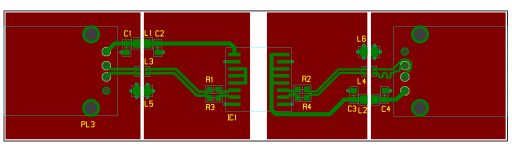
Firstly the design I put up is a generic USB isolation interface, the only difference from the generic interfaces is the deliberate isolation of the grounds and lines via moats, bridged by a ferrite bead for the Ground, a pi filter for the 5V and the common mode choke for the USB lines. This layout is effective at reducing parasitic capacitive coupling (one of the main coupling mechanisms for high frequency noise, such as found in digital data), the ferrites and pi filter proving high frequency filtering (this can be tailored by the choice of ferrites and capacitor values).
In this instance, as in most uses of Adum USB isolation in electronic equipment, the Adum is not to isolate noise, but to isolate one piece of gear from another from overvoltage. This interfaces main function is to protect the main unit from a sub unit going bang and causing high voltage to appear on power and signal lines, thus the main unit goes on working (in this particular case you want it to work, it’s from some medical kit we worked on).
The main point of me posting this design is to show how to isolate USB when using a filter, if you don’t have defined moats clear of copper you are going to get capacitive coupling rendering the filter useless. The design in question and the layout techniques was developed for some other equipment, where as I said I worked with an RF engineer where we achieved immunity up to 18GHz, so the layout and filtering has been tested and measured and proven to work.
Further to jitter through the Adum, there have been threads where this device is used and I believe there may be some jitter figures. The data sheet gives a figure of 3ms and some other figures for data transition, that sort of thing, I leave to the electronic engineer I am working with. My concern is providing the best physical interface for the signals and power to travel around and provide the best signal integrity and noise immunity from said layout. The Adum’s are only good for USB full speed, though again from discussion on another recent thread I do believe this will cater for even high res audio over USB.
The point I am trying to get across is that if you are going to do a filter product then it needs to be done correctly, and physical layout is paramount, done incorrectly it negates the filtering. In this instance the layout inside the jitterbug is not optimal and there are numerous coupling paths for the noise. I would have used the techniques shown in my layout as I know for certain that these work having been proven on numerous bits of kit (measurements and data is covered by NDA's and other restrictions).
What I have found interesting is the gushing praise for this device on other forums, without examining the internals, looking at USB specs or anything, it like many other questionable audiophile products seem to be just accepted without any data backup, just some wonderful marketing prose. Thankfully the world has DIYaudio where we can still discuss these things in a true fashion (though occasionally little narrow minded people will resort to calling people like myself (daring to ask for data) jerks, small minded and that my views have no relevance)…
I not major busy at the moment so I will have a look at removing the Adum and adding heavier filtering for the 5Vs.
")
In this instance, as in most uses of Adum USB isolation in electronic equipment, the Adum is not to isolate noise, but to isolate one piece of gear from another from overvoltage. This interfaces main function is to protect the main unit from a sub unit going bang and causing high voltage to appear on power and signal lines, thus the main unit goes on working (in this particular case you want it to work, it’s from some medical kit we worked on).
The main point of me posting this design is to show how to isolate USB when using a filter, if you don’t have defined moats clear of copper you are going to get capacitive coupling rendering the filter useless. The design in question and the layout techniques was developed for some other equipment, where as I said I worked with an RF engineer where we achieved immunity up to 18GHz, so the layout and filtering has been tested and measured and proven to work.
Further to jitter through the Adum, there have been threads where this device is used and I believe there may be some jitter figures. The data sheet gives a figure of 3ms and some other figures for data transition, that sort of thing, I leave to the electronic engineer I am working with. My concern is providing the best physical interface for the signals and power to travel around and provide the best signal integrity and noise immunity from said layout. The Adum’s are only good for USB full speed, though again from discussion on another recent thread I do believe this will cater for even high res audio over USB.
The point I am trying to get across is that if you are going to do a filter product then it needs to be done correctly, and physical layout is paramount, done incorrectly it negates the filtering. In this instance the layout inside the jitterbug is not optimal and there are numerous coupling paths for the noise. I would have used the techniques shown in my layout as I know for certain that these work having been proven on numerous bits of kit (measurements and data is covered by NDA's and other restrictions).
What I have found interesting is the gushing praise for this device on other forums, without examining the internals, looking at USB specs or anything, it like many other questionable audiophile products seem to be just accepted without any data backup, just some wonderful marketing prose. Thankfully the world has DIYaudio where we can still discuss these things in a true fashion (though occasionally little narrow minded people will resort to calling people like myself (daring to ask for data) jerks, small minded and that my views have no relevance)…
I not major busy at the moment so I will have a look at removing the Adum and adding heavier filtering for the 5Vs.
Nice replies, really interesting.
I think the Jitterbug is like mains filtering. There is no way of creating a generic filter that works in each and every application. It all depends on the source output characteristics and the load. That's why a lot of people think that mains filtering kills dymamics. Yes, completely true if the filter does not match the load, wich is almost always the case becuase most people think that a filter wich is specced for 16A load would have better results (less resistance) then a lower specced filter. The opposite is true however. So in the case of the Jitterbug I guess (yes I can only guess I'm afraid) that it all depends on the USB host. Does it allready have some form of filtering on it's output to meet the IEC standard, etc.
Today I have tried the Jitterbug on a fifth computer, my good old Toshiba NB100 netbook. Off all my computers (seven in total) this little bugger always had the best sounding USB ports on it's own and suprise suprise, it's the only one where the Jitterbug seems to work flawlessly, No hickups. Soundcards are all being recognized and I do not have to unplug and plug it every boot sequence. Does it improve the sound quality. Well actually it does, a little, and I mean just a little but noticable. just a tad bit less glare and a bit better defined highs, still a worthwile improvemnets although again very little. Don't expect any miracles here, everything will sound just the same as before, just a tiny bit cleaner.
My advice would be to arrange a moneyback arrangement in case it does not work. In my case it only worked on one out of five computers. Might depend on the souncard as well. The ones I have tried where a Nuforce Udac, a BD design NOS USB dac (don't know what chip is being used, it's just being recognized as "USB Audio DAC" and a Focusrite Scarlett 2i4. Computers where my Shuttle desktop, custom build as music server, running XP, an older Averatec laptop running XP, an ASUS i7 ultrabook from 2012 running win8.1. A Macbook pro retina from 2014 running OSX Mavericks (10.9.5) and a Toshiba netbook, also running XP.
Yes, that a lot of XP machine. I'm still running XP on my music server with older drivers into a RME Fireface. This PC is optimized this way and a clean install of win 7 sounded worse so I went back to XP and have never looked back.
Unlike mains the USB bus is strictly specified, like Ethernet interface. There has to be a strict set of guidelines to work to as in theory any USB device should work plugged into any USB controller (in theory anyway). Laying out USB interfaces becomes second nature when you do lots of boards as they are all basically the same, with minor differences. The critical requirements such as a 90R differential impedance for the bus are always followed, generally the same with line filters and resistors. Some will add transient protection some wont.
What would worry me is any decent equipment that does not have at least the basic filtering, the main reason for this filtering (as many cynics will attest) is to keep the internal noise from the host device from radiation from the USB cable for CE, FCC etc. certification.
Anyway it should be quite interesting as this thread has been put up on another forum by one of my old sparring partners from here SandyK, so I expect some comments... That said I stand by my opinion that the layout is essentially flawed for what is being claimed for filtering...
I'll have to have a look later, the traces are done for 90 R differential impedance, suspect the PCB was less than 1.6mm to get this impedance without t6racks about an inch thick.
I tend to use Saturn PCB toolkit for initial impedance figure, then fine tune it using myy SIV add on or talk to the PCB manufacturer who uses Polar software.
The design was thrown together mainly to show how to do the isolation, the original board was a 8 layer, with multiple ground planes so signals always had a return layer next to them.
Will open design up tomorrow as I have a hospital appointment....
Computer Audiophile, Audioquest jitterbug.
Last edited:
The jitterbug is a basic filter, that is all.
Doesn't mean it doesn't work. They do make some additional claim about taming 'resonance'. Not sure what they mean here or if it's something additional to the filtering.
There is only so much you can do with the data lines, hence the use of a USB common mode choke on the lines, that is all you can really do.
Pretty much what I am playing with at the moment.
Anything else is likely to alter the differential impedance of the lines further adding to signal integrity problems.
Or cause additional jitter if one is not careful.
- Status
- This old topic is closed. If you want to reopen this topic, contact a moderator using the "Report Post" button.
- Home
- Source & Line
- PC Based
- Quick Audioquest Jitterbug review