Pafi said:
Ez nem jellemzõ. Az elkó nagy frekin ellenállás, tipikusan ide méretezik a vágási frekit, így a szûrõ csak 90 fokot tol, sima P szabályzó (a precizitás miatt PI) elég. De most már nem offolok tovább.
Az elkó nagy frekvencián induktivitás. Az ESR okozta zérus általában nagyobb mint Fs (1/(2*pi*Resr*C)). A modulátornak Ts/2 holtideje van, ami lineáris fázis. Fs-nél pont 180 fok. Emiatt lentebb kell vinned a zérust egy soros ellenállással, hogy legyen fázistartalék. A soros ellenállás pedig nem biztos hogy megéri. PI-vel nem tudod megcsinálni, mert annak konstans -90 fokos fázisa van. P-vel, vagy PID-vel lehet. Akkor is az elõbb említett dolgok miatt ellenállással, vagy fs= .. MHz körül, ami viszont a hatásfok miatt nem éri meg.
Nem véletlenül használnak Low-ESR kondenzátorokat sem a kapcsolóüzemû cuccokban.
Pafi said:
I have no idea what you are talking about.
Pafi wrote that a PSU regulator doesn't necessarily contains differentiator zero-pole pair, because of the output capacitor's ESR. I think the ESR is not large enough to provide an achieveable good phase margin at cutoff, because of the modulator's linear phase characteristic, which is inversely proportional to the switching frequency (Fs). So a modulator in a PSU working at Fs=100 kHz switching frequency has -180 degrees phase at Fs. And the zero caused by the ESR is beyond that range (1/(2*pi*Resr*C)). If there is no differentiator zero-pole pair in the regulator, a series resistor could be used with the output capacitor lowering the zero's frequency caused by ESR. But this is not closely belongs to the original issue.
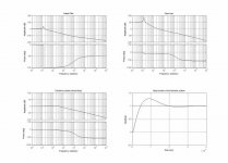
For example, I attached a picture of the control loop characteristics about an Fs=100 kHz working PSU, with Lchoke=100 uH, Cout=6000 uF Yageo LG at the secunder side. The linear phase is approximated with 4-th order pade function. It's easy to see the modulator's linear phase removes the phase margin could be caused by ESR. The regulator utilizes a PD differentiator with fzero=3 kHz, and fpole=200 kHz.
Attachments
I think the ESR is not large enough to provide an achieveable good phase margin at cutoff
Electrolytic capacitors have a different opinion!
 They think they have a pure ohmic impedance at switching freq. Thats why the ESR is so important!
 Check real values:
http://www.yageo.com/pdf/yageo/E-Cap_Radial_SX_2006.pdf
Eg.:2200 uF 35 V elco have an ESR of 44 mohm, so corner freq is 1,6 kHz, not >100 kHz, as you believed! (And this is the low-ESR series!)
because of the modulator's linear phase characteristic, which is inversely proportional to the switching frequency (Fs). So a modulator in a PSU working at Fs=100 kHz switching frequency has -180 degrees phase at Fs.
Sorry, you are wrong again! PW modulators have insignificant phase shift, because they are "naturally sampled"! (You must have learned something like sampling have a delay, but that's not true! Sampling+hold have a delay assumpted by Ts/2, but sampling itself don't have a shift at all, and in a PWM modulator there is no hold!)
PI-vel nem tudod megcsinálni, mert annak konstans -90 fokos fázisa van
Hát ezt meg ki mondta neked? Mióta nincs valós része az 1/(j*omega)+1 függvénynek?!? Összekevered a tiszta I típusú szabályzóval! Egyébként meg ezeket a "nem tudod megcsinálni" elméleteidet azoknak az áramköreimnek meséld el, amik gond nélkül mûködnek a PI szabályzóval!
Ps.:
Please don't quote my question if you don't want to answer it (or if you don't know what it refers to)!
Pafi said:
Please don't quote my question if you don't want to answer it (or if you don't know what it refers to)!

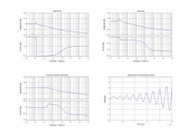
So, you are right. I calculated much more faster zero for LG series wrong. I remembered that we learnt about Ts/2 in the "Elektronika 3" subject. But the Fourier series of naturally sampled PWM really doesn't contains it. Maybe we learnt only for overestimate the parasitic delays. For PI I thought about a series P and I, which is really a simple I. Now I simulated the VMC with paralleled P and I regulator and proper ESR value, and it works. Thanks!
Attachments
Yes, I will estimate the phase delay of the optocoupler, the primary stage, and the rectifier stage and maybe reduce it. But at now there are a lot of EMI problems still in the controller stage. The regulator is unstable at certain pulse widths, and the transformer is chirping when become saturated and current limit occurs. CMC would be better, but I can't measure primary current (at the moment, there is an EMI-coupled current limit sensing ). I should to redesign the whole PCB. But the PI controller works! I will send pictures if I will have spare time, but at now I have to learn.
Regards,
Gyula
). I should to redesign the whole PCB. But the PI controller works! I will send pictures if I will have spare time, but at now I have to learn.Regards,
Gyula
@Pafi & Gyula:
Folks, I really appreciate you enthusiastic discussion about the thread DVBjunky has started. But I must complain the posts (possibly) written in your native language which not every member of this forum can read and understand though!!!
Please stay with english and everything will be just fine.
Back to the issue with large bulk caps in the range of tenthousands of microfarads connected to a SMPS:
All the poles and zeros for the closed loop control you have mentioned are interesting as long as it belongs to a loads being in the power range where the SMPS was designed for. With large bulk capacitors and a standard audio signal supplied to an amplifier you have to take much more attention about the current limiting scheme of the SMPS.
An example might make that more clearly:
Considering an (class-D) amplifier capable of delivering 300W at 4 ohm and an efficiency of 85% the necessary max. power consumption would be about 353W. For simplicity (any losses are not considered) we say the power supply voltage must be at least +/-50V. Therefore the secondary average current capability of the supply must be round about 3.5A.
And that's exactly the point I want to mention: The average power consumption is not equal the peak power consumption, because in the mentioned case the peak (secondary) power would be approx. 12.25Apeak times 50V equals 612.5W. This is far beyond the limit the SMPS is designed for.
Therefore this energy is supplied by the bulk capacitors resulting in a decrease of the rail voltages.
In a closed loop controlled SMPS the regulator will detect this drop and tries to prevent that drop by "pumping" more energy from the primary side to the secondary side. If the SMPS has a tight control loop it will rapidly reach the current limiting region of the primary switching transistor(s) to protect them from any destruction (hopefully). Depending on this control loop / current limiting scheme the stabilty of the output voltage of that SMPS may be OK, starts to oscillate (worst case) or just shuts down (best case).
In all my decades of experience in repairing/modifying/using/abusing SMPS I've seen one SMPS starting with oscillations and most of them just shut down (when raising the volume to the maximum) because they detected an overcurrent condition.
After all, without going to deep into actual component (value) selection, the control loop (design) is highly responsible for it's capability to "drive" large capacitive loads. If you have a glance at schematics of professional PA amplifier manufacturer you'll find different designs for their amps equipped with SMPS. Their control loops (if there is any) and over-current sensing scheme is different from those designed for PC components (mainboards, etc.).
That's the main reason why I stated to unsolder the bulk caps of those cheap (for PCs stuff designed) SMPS. With SMPS particularly designed for audio amplifiers big bulk caps won't hurt at all.
Because of the high(er) switching frequency (if compared to the mains frequency of 50/60Hz) the bulk caps don't need to be that big anyhow - the gap isn't anymore in the millisecond range, it's now (with SMPS) in the microsecond range!
Corax!
Sorry, I need very much effort to tell some things in english.
I don't really understand this! OK, the "gap" is short, or even non-existant (inductor, continuous mode), but does this mean, that you can use very small cap? I don't think so! Most PWM amp needs very small supply impedance even at low freq, and some current sinking capability.
...
Shut down style overcurrent protection is not good for amps, indeed.
Current limiting can have a time-dependence, for short time (some seconds) one can allow higher (eg. 2X) current. In many cases this can be achieved by a capacitor+resistor in current feed-back loop (and proper selection of saturation current of inductor, etc...).
Sorry, I need very much effort to tell some things in english.
Because of the high(er) switching frequency (if compared to the mains frequency of 50/60Hz) the bulk caps don't need to be that big anyhow - the gap isn't anymore in the millisecond range, it's now (with SMPS) in the microsecond range!
I don't really understand this! OK, the "gap" is short, or even non-existant (inductor, continuous mode), but does this mean, that you can use very small cap? I don't think so! Most PWM amp needs very small supply impedance even at low freq, and some current sinking capability.
...
Shut down style overcurrent protection is not good for amps, indeed.
Current limiting can have a time-dependence, for short time (some seconds) one can allow higher (eg. 2X) current. In many cases this can be achieved by a capacitor+resistor in current feed-back loop (and proper selection of saturation current of inductor, etc...).
@Pafi:
Let's say we've a mains frequency of 50Hz (common in Europe), transformed and bridge rectified, giving us a rectified sinewave with a frequency of 100Hz. For simplicity reasons let's say this results in a 10 millisecond gap between the sine peaks where the bulk capacitor acts as a voltage/current source.
In a SMPS switching i.e. at a PWM frequency of i.e. 50kHz (and again "bridge" rectified at the secondary) the gap is now just 10 microsecond long. For the same voltage drop across that bulk capacitor the value can be 1000 times smaller than in the conventional non-switching power supply.
The rule of thumb for the bulk capacitor value on conventional power supply is usually 2000µF per Ampere for a moderate voltage drop (more doesn't really hurt - except the rectifier - but you may have a low tide in your wallet when considering the cost estimates). In many common SMPS which deliver for instance +5V / 20A the bulk capacitor is often in the range of just 220µF...1000µF. Of course it must be a low ESR type caused by the high and fast (switching frequency) ripple current of SMPS.
Another important point I wanna mention is that a saturation of the power transformer should be avoided under all circumstances. If you drive the power transformer into saturation you make the effect worse. It will in addition limit the current in the secondary, hence further increasing the voltage drop.
For absolute values it might give us a headache.
The often heard but not so well known ESR parameter for capacitors will give us an estimate on how good the capacitor might be. Without knowing at which frequency this value is measured I wouldn't give a damn about it. The ESR (Equivalent Series Resistance) is often measured at a very low frequency (very common is 100Hz). Considering a SMPS running at a frequency of 100kHz what does this value still mean?!? I got a few caps with almost perfect values for ESR (measured at 100Hz) of less than 30 milliohm. But I would never ever use them in a SMPS because of their reactive value (inductance) at 100kHz. The ESR depends also on the measurement frequency. If in doubt have a look at a full datasheet. It is important to consider all parameters of a capacitor under all circumstances and in the range of interest (i.e. frequency, ...).
In common SMPS designs the output bulk capacitor is the only component which is capable of sinking current, hence a rise in the ouput voltage will occure. SMPSs working in CCM (continuous current mode) better be capable to switch to DCM (discontinous current mode) to prevent any fatal high output voltages by stopping the energy transfer from the primary to the secondary side.
Yes, in deed, it does...., but does this mean, that you can use very small cap?
Let's say we've a mains frequency of 50Hz (common in Europe), transformed and bridge rectified, giving us a rectified sinewave with a frequency of 100Hz. For simplicity reasons let's say this results in a 10 millisecond gap between the sine peaks where the bulk capacitor acts as a voltage/current source.
In a SMPS switching i.e. at a PWM frequency of i.e. 50kHz (and again "bridge" rectified at the secondary) the gap is now just 10 microsecond long. For the same voltage drop across that bulk capacitor the value can be 1000 times smaller than in the conventional non-switching power supply.
The rule of thumb for the bulk capacitor value on conventional power supply is usually 2000µF per Ampere for a moderate voltage drop (more doesn't really hurt - except the rectifier - but you may have a low tide in your wallet when considering the cost estimates). In many common SMPS which deliver for instance +5V / 20A the bulk capacitor is often in the range of just 220µF...1000µF. Of course it must be a low ESR type caused by the high and fast (switching frequency) ripple current of SMPS.
Indeed!!! But a PC power supply should trip rapidly when an overcurrent condition occures to protect your expensive equipment, like mainboard, CPU, ...Shut down style overcurrent protection is not good for amps, indeed.
According to my mentioned example (300W@4ohm) the overcurrent trip point must be in the range of at least 4x the value of the average current (12.25A / 3.5A = 3.5). This means a lot of stress for certain components like the switching (and driving) transistor(s) and the power transformer (avoiding saturation at peak current).Current limiting can have a time-dependence, for short time (some seconds) one can allow higher (eg. 2X) current.
Of course an RC low-pass filter can be implemented, but it could make the regulation very "soft" with improper component value selection. If the time constant is to high there's no big difference (concerning the output regulation) anymore between this "soft" SMPS and a non-controlled at all SMPS. The voltage drop will raise with increasing current consumption. The output ripple voltage will increase. Well, almost the same behaviour as with conventional power supplies - just the frequency could be different/varying.In many cases this can be achieved by a capacitor+resistor in current feed-back loop (and proper selection of saturation current of inductor, etc...).
Another important point I wanna mention is that a saturation of the power transformer should be avoided under all circumstances. If you drive the power transformer into saturation you make the effect worse. It will in addition limit the current in the secondary, hence further increasing the voltage drop.
Well, that any switching and in particular PWM desire low impedance paths from the power supply is out of question.Most PWM amp needs very small supply impedance even at low freq, ...
For absolute values it might give us a headache.
The often heard but not so well known ESR parameter for capacitors will give us an estimate on how good the capacitor might be. Without knowing at which frequency this value is measured I wouldn't give a damn about it. The ESR (Equivalent Series Resistance) is often measured at a very low frequency (very common is 100Hz). Considering a SMPS running at a frequency of 100kHz what does this value still mean?!? I got a few caps with almost perfect values for ESR (measured at 100Hz) of less than 30 milliohm. But I would never ever use them in a SMPS because of their reactive value (inductance) at 100kHz. The ESR depends also on the measurement frequency. If in doubt have a look at a full datasheet. It is important to consider all parameters of a capacitor under all circumstances and in the range of interest (i.e. frequency, ...).
Till now I haven't seen any PC-SMPS capable of really sinking current. Such a "bleeding" circuit would mean additional costs and complexity and will be therefore avoided in most cases. However I've seen many (more or less) conventional (and switch-mode) lab power supplies having this circuit, primarily designed to drive reactive loads (in particular inductors)...., and some current sinking capability.
In common SMPS designs the output bulk capacitor is the only component which is capable of sinking current, hence a rise in the ouput voltage will occure. SMPSs working in CCM (continuous current mode) better be capable to switch to DCM (discontinous current mode) to prevent any fatal high output voltages by stopping the energy transfer from the primary to the secondary side.
The allowable current ripple also limits the minimal value of the output capacitor for a given series. The lifetime also depends on the temperature and the current ripple. A full-bridge discharges and charges the supply capacitors with square-like pulses with the value of output current, much greater than the output inductor ripple. So I think the output capacitor should be oversized to endure this effect.
Yes, in deed, it does...., but does this mean, that you can use very small cap?
Let's say we've a mains frequency of 50Hz (common in Europe), transformed and bridge rectified, giving us a rectified sinewave with a frequency of 100Hz. For simplicity reasons let's say this results in a 10 millisecond gap between the sine peaks where the bulk capacitor acts as a voltage/current source.
In a SMPS switching i.e. at a PWM frequency of i.e. 50kHz (and again "bridge" rectified at the secondary) the gap is now just 10 microsecond long. For the same voltage drop across that bulk capacitor the value can be 1000 times smaller than in the conventional non-switching power supply.
10 us gap? With filter inductor, or at maximal duty cycle with ideal trafo there is no gap! Does this mean you dont have cap at all? Not, of course! You didn't tell anything about the phisics of these thing, just assume proportionality. But who said that filter cap have only one task? Nobody! There are others, and some of them does not changes! Eg.: I told amp can pump back current to PS. In this topic the question was about a bridged amp, where this effect is moderate, but in a single ended amp this is enormous, and definitely requires a big cap especially at 20 Hz drive. You can't decrease filter caps as you like in these cases!
But a PC power supply should trip rapidly when an overcurrent condition occures to protect your expensive equipment, like mainboard, CPU,
Who said that time-dependent current limit can't respond immediately (at a higher current, which is still safe for a short time)? Anyway: I didn't tell about PC supply! I never use them for audio!
According to my mentioned example (300W@4ohm) the overcurrent trip point must be in the range of at least 4x the value of the average current (12.25A / 3.5A = 3.5).
Not really. You have forgot that the 4x current arises only on one of the supply rails, while on the other there is no current, which means that on primary side there is only 2x overload (as I wrote). Only one wire of output inductor and diodes see 4x current, but they will happily live with this. But if you don't want this, you can drive channels in opposite phase (and reverse one of the output connector). This has some other benefits.
This means a lot of stress for certain components like the switching (and driving) transistor(s)
For a 20-30 A MOSFET this is not a big deal. Semiconductors have become soo cheap that 2-4x oversizing is not a chalange anymore. Especially when overcurrent duration is strongly limited. Eg. I use 32A 500V FETs in the supply of my 800 W amp. Do you think there will be any problem with 2x (12A) current?
and the power transformer (avoiding saturation at peak current).
Saturation? How does it come here? Load current doesn't cause saturation. It's magnetizing current, but it does not increasing with load current!
Of course an RC low-pass filter can be implemented, but it could make the regulation very "soft" with improper component value selection. If the time constant is to high there's no big difference (concerning the output regulation) anymore between this "soft" SMPS and a non-controlled at all SMPS. The voltage drop will raise with increasing current consumption. The output ripple voltage will increase. Well, almost the same behaviour as with conventional power supplies - just the frequency could be different/varying.
Do you really believe there can't be two independent controll loop in a power supply? Current limit loop doesn't effect voltage stabilisation loop at all (if you do it properly). Trust me, it works, i tried! It's not a 1 order RC filter. It forms a pole and a zero one octave from each other!
I got a few caps with almost perfect values for ESR (measured at 100Hz) of less than 30 milliohm.
This is rather irrelevant. This is the smaller (real) pomponent of impedance. Imaginary component (Xc=1/(omega*C)) is much higher, so this is relevant! Small C-> high impedance! Impedance is Real+j*Imag ! And amp consumpts audio freq current too, not only switching freq! Down to 20 Hz!!!
Till now I haven't seen any PC-SMPS capable of really sinking current.
Only 0,1 A. Yes, they aren't designed for audio.
@Pafi:
My expectation is that DVBjunky hasn't these high skills to understand right away and completely how a SMPS functions - otherwise he wouldn't ask here for support.
What you do yourself when designing your own (DIY) power supply is a completely other thing.You can chose the headroom you want and don't have to take care (that much) about the final price for it. Of course it should be favorable and not to expensive, but the limits are set by yourself.
I was trying to give an inside view of what could happen (in worst case, even if this would be a seldom exception).
Well after all, I guess we've said almost everything and (much) more then DVBjunky wants us to tell him.
I just wanted to find some sort of metaphor to explain why the cap can be smaller in SMPS. I guess I've chosen the wrong one why you jump on it immediately.10 us gap? With filter inductor, or at maximal duty cycle with ideal trafo there is no gap! ...
My expectation is that DVBjunky hasn't these high skills to understand right away and completely how a SMPS functions - otherwise he wouldn't ask here for support.OK, but DVBjunky, who started this thread, was asking for using a SMPS, which is probably designed for PC/laptop/..., for his AMP4. And those SMPS have their specific disadvantages for audio amplifier (ab)use.... Anyway: I didn't tell about PC supply! ...
I must admit I made a tiny mistake here. Some lack of concentration, I guess.... You have forgot that the 4x current arises only on one of the supply rails, ...
Believe me or not, while I'm repairing SMPS of the last decades the component selection for many (if not most) of these consumer eklectronics parts are at their limits. For a mass production (we're talking here of ten thousend to hundred thousend units) it is a question of money and if they can even save a single cent on each power transistor with a less max. current capability they will chose this "weaker" part.For a 20-30 A MOSFET this is not a big deal. Semiconductors have become soo cheap that 2-4x oversizing is not a chalange anymore. Especially when overcurrent duration is strongly limited. Eg. I use 32A 500V FETs in the supply of my 800 W amp. Do you think there will be any problem with 2x (12A) current?
What you do yourself when designing your own (DIY) power supply is a completely other thing.You can chose the headroom you want and don't have to take care (that much) about the final price for it. Of course it should be favorable and not to expensive, but the limits are set by yourself.
Of course is the load current (on the secondary side) not directly responsible for any saturation of the power transformer. With a bad design (for the wrong purpose) of the control loop it could be the case indirectly. When to much power is pulled from the secondary the control loop tries to pump more energy into the primary (in simple words) may driving the duty cycle into a range where the transformer starts to saturate. Just to make sure, we're talking here about an unknown SMPS. We do neither know the schematic nor how it's practically carried out. I've seen SMPS suffering on these effects.Saturation? How does it come here? Load current doesn't cause saturation. It's magnetizing current, but it does not increasing with load current!
I know there're many schemes with local/global and/or multiple feedbacks with more or less success in regulating the output voltage, current limiting bahaviour, etc.Do you really believe there can't be two independent controll loop in a power supply? ...
I was trying to give an inside view of what could happen (in worst case, even if this would be a seldom exception).
I already mentioned that here (but not with the formula):... Imaginary component (Xc=1/(omega*C)) is much higher, so this is relevant! ...
... But I would never ever use them in a SMPS because of their reactive value (inductance) at 100kHz. ...
Well after all, I guess we've said almost everything and (much) more then DVBjunky wants us to tell him.
- Status
- This old topic is closed. If you want to reopen this topic, contact a moderator using the "Report Post" button.
- Home
- Amplifiers
- Class D
- Question: SMPS switching frequency with 41Hz Amp4