")

Hello Titanchen68
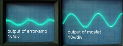
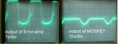
Lower or completly remove R33, or put a bigger C38, 1uF is not enought to feed the power required by 6 mosfet...Look like that the IR2110 go into undervoltage lockout when you try to much power from it. That's why error amp try to compensate.
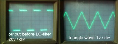
Reduce by the way your traingle wave amplitude, you will get better linearity.
Fredos
www.d-amp.com
Lower or completly remove R33, or put a bigger C38, 1uF is not enought to feed the power required by 6 mosfet...Look like that the IR2110 go into undervoltage lockout when you try to much power from it. That's why error amp try to compensate.
Reduce by the way your traingle wave amplitude, you will get better linearity.
Fredos
www.d-amp.com
Fredo:
Thanks for your replying..!!
I will try all the suggestion you said .!!
I will reduce the triangle wave to 2Vpp.
Bigger the R27 to 100K ohms.
Remove the R33.
About the feedback network ....
could you teach how to design the component value ???
The capacitor parallel with the feedback resistor .
Will the cap bigger and less effect the phase ???
I did not found any good ''real life'' way to calculate accurately the feedback network. However, I will give you some real trick to ''adjust'' it. First only leave the feedback resistor in the feedback loop. Put a big capacitor (1-2.2uf) at the output with a 4 ohms load. Check if the amplifier is stable with and without 4 ohms load. If yes remove the cap and play with a small value (2.7-47pf) over your feedback resistor. If not, add capacitor from 47 to 220pf over feedback resistor to reach stability when you remove 4 ohms load. After this check stability when you remove the capacitor you add. Add a resistor-capacitor network over the existing network to get stability like you did on your schematics (C28 and R35), but always keep R35 to the same value of the feedback resistor (R31).
Wish that will help you!
Fredos
www.d-amp.com
Wish that will help you!
Fredos
www.d-amp.com
fredos said:I did not found any good ''real life'' way to calculate accurately the feedback network. However, I will give you some real trick to ''adjust'' it. First only leave the feedback resistor in the feedback loop. Put a big capacitor (1-2.2uf) at the output with a 4 ohms load. Check if the amplifier is stable with and without 4 ohms load.
[/url]
Is stabel mean paly with some signal???
Now , I just use a 55ohm resistor be the Load...
Is it too big ??
Make test at 4 ohms, that good begining to get stability into 2 and 8 ohms..
Open load test is for stability purpose, but at 55 ohms, it's look like open load for me!
Fredos
www.d-amp.com
Open load test is for stability purpose, but at 55 ohms, it's look like open load for me!
Fredos
www.d-amp.com
Fredos:
Ya , It get working , when i remove the R33 .
The output amplitude can reach to +/- 45v.
But still can not reach to +/- RAIL .
But when the amplitude reach to +/- 45v , It get clip and distortion.
And current get higher very much .
I don't know is that get wrong ????
I will post some pic later , because i just burned out the mosfet.
When the input signal get clip ,,, the output mosfet maybe too hot to burned out.
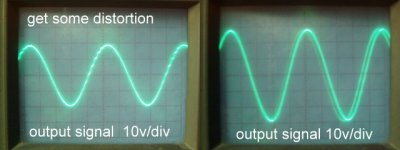
The pic shown that 20Vp output waveform, and 30Vp output waveform.
But It get some strange thing ...
When output amplitude reach to 20Vp , we can see some distortion at rise side.
But on 30Vp , it became better.
I don't know why ,,,,,,
The pic about 30Vp , it get some shadow , that cause by my oscilloscope.
I will try to adjust the capacitor over the feedback loop.
now , i use 68pf capacitor.
Attachments
Tekko :
Thanks a lot ,,,, It very important for me ,,,
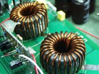
So , It must using 2-material for class-d .....
That why i always get some ripple on output,,,,
Thanks again ....
I'm sorry , i just ask the manufator ,
He said it is T184-2 material ,,,,,, not T0-26
I get some wrong ,,,, sorry about it
Thanks a lot ,,,, It very important for me ,,,
So , It must using 2-material for class-d .....
That why i always get some ripple on output,,,,
Thanks again ....
I'm sorry , i just ask the manufator ,
He said it is T184-2 material ,,,,,, not T0-26
I get some wrong ,,,, sorry about it
I just buy a 4 ohms 500W Load .
And try to test the class-d again with the 4 ohms LOAD.
I test the "pre-filter feedback" class-d amp ,i did before.
It seems not good enough , I add the signal from a function generator.
When the output of the amplifiter less than 35v , the output wave is good.
when amplitude near to 40v , get some oscillation on the top of the sine wave.
And It get clip at 38v , i don't have any ideal now.....
Before i tyr it with a 55 ohms , it can get 55v amplitude when clip.
When the load get lower, it seems can't get enought drvier current.
My bootstape cap is 33uF/25v , using 6 output mosfet , three per side.
I didn't add any resistor between power supply and VCC,Vdd of IR2110.
IR2110's Vcc and Vdd , i using a 7815 be the power regulator.
Does the output current of 7815 not enough???
- Status
- This old topic is closed. If you want to reopen this topic, contact a moderator using the "Report Post" button.
- Home
- Amplifiers
- Class D
- question :post filter feedback