No..... and it is a fairly simple topology BION
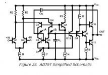
The simplified schematic shows a diff pair with a folded cascode and a current mirror load. This is followed by two stages of emitter followers. This is simple schematic showing only the basic outline of the signal path. But as op amps go this is a pretty simple topology and not near as convoluted as many I have looked at.
Bias compensation:
http://www.analog.com/library/analogDialogue/Anniversary/6.html
Someone will read it eventually I suppose..
Attachments
Hi Sy:
>the 797's diff input is cascoded, current mirrored, and bootstrapped six ways from Thursday. Is that possibly the reason for the low bias current?<
The cascode part of the 797 is of the inverted/folded type, which is good for stability and bandwidth, but AFAIK, means little for the base or bias currents of the input diff pair. The second-stage current mirror just sums the plus and minus portions of the signal into a pushpull output, with probably very little effect on the input base or bias currents.
Finally, the major bootstrap mechanism in the AD797 maintains a constant voltage across the summing current mirror, which will kick up the OL gain a lot, and I think will also help the PSRR on the minus voltage rail. But again, I doubt if this represents any direct advantage for input base or bias currents.
Of course, there is always the possibility that the real AD797 circuit is far more intricate than what Analog Devices chose to publish.
best, jonathan carr
Pavel: My some-times engineering design partner, Petr Mares, is originally from Czech, and he is also the person who designed and programmed most of the Connoisseur website.
We haven't done anything in the Czech Republic yet, but who knows what the future may bring?
regards, jonathan carr
We haven't done anything in the Czech Republic yet, but who knows what the future may bring?
regards, jonathan carr
"Of course, there is always the possibility that the real AD797 circuit is far more intricate than what Analog Devices chose to publish."
That is why it says simple schematic on the drawing from the data sheet. I feel quite sure this is nowhere near the actual circuit and would image that the bias compensation network is one of the bits not shown. Op amps are very proprietary. The reason Spice models are grossly simplified macromodels is for both the protection of the design and lengthy simulation time for a model that represented the real complexity of the design.
http://www.linear.com/pub/document.html?pub_type=app&document=51
Fred Dieckmann said:(...)The reason Spice models are grossly simplified macromodels is for both the protection of the design and lengthy simulation time for a model that represented the real complexity of the design.
http://www.linear.com/pub/document.html?pub_type=app&document=51
This is a bit off-topic, but to add to what Fred has mentioned, some of the SPICE op-amp models are really poor. In LTSpice for example, all of the Linear Technology op-amp models have the property that the simulated supply current does not change as a function of the output current delivered! I believe this is a property of the Boyle model. The Analog Devices op-amp models are much better. There's an application note describing them here:
http://www.analog.com/UploadedFiles/Application_Notes/48136144500269408631801016AN138.pdf
If I ever need an op-amp model for SPICE, I try to grab the Analog Devices model if I can find one.
Hi,
Exactly.
Cheers,")
That is why it says simple schematic on the drawing from the data sheet. I feel quite sure this is nowhere near the actual circuit and would image that the bias compensation network is one of the bits not shown.
Exactly.
Cheers,
Yes, that would have been useful to know. Although one can
often design for equal impedances, it is not always so.
One of the reasons I have been interested in the noise issues
recently is that I plan to build a simple low-noise diff. amp for
measurement purposes. In this case it is, of course, impossible
to have any control over the source impedance. I had planned
to use LT1115s for the front end, but the more I think about it,
especially after reading this thread, the more I get the feeling
that FET-input op amps might be a better choice after all. I
suppose the best I can do is to get som reasonbly low-noise
FET-input amps too and compare the two choices empirically
for various source impedances and try to make up my mind
which of the two seems the best compromise. (Yes, I could
use bipolar op amps and use discrete low-noise JFETs in
front of them, but I am not trying to build the best possible
design, just something simple but useful).
SY said:It really gets down to what the anticipated range of source resistances is. For low, bipolar; for high, FET.
Yes, I know. However, given what has been said here on bias
compensation, one wonders if bipolar is perhaps not even a
very good choice for low source impedances since impadances
may be quite mismatched. Well, as Marcel said, it is anybodys
guess, so probably experiments are the best way to answer
the question.
OK, measurement (sorry), but what is the signal source?Christer said:Per-Anders,
I told a few posts ago what the use is.
Maybe you should look into chopper stabilized? MAX420, MAX430, LT????, ICL7650 etc.
What is the required S/N? Bandwidth?
Well, the typical thing with measurements is that the source
varies from case to case.
Anyway, I will use it as a preamplifier for scope and soundcard
to measure small signals, including noise measurements, in
relation to audio. Low noise is thus important. Precision DC
measurements are not intended, so I guess chopper stab.
amps are not interesting. The plan is to build something
based on the standard three-op-amp instrumentation amplifier,
using low-noise op amps at the front. The question, thus, is
whether to stick to low-noise bipolars or use some reasonably
low-noise FET ones?
Maybe not....
"It really gets down to what the anticipated range of source resistances is. For low, bipolar; for high, FET."
Actually there some jfets with lower noise
the SK389 that are quite frequently used
in moving coil and other low noise applications. Higher current noise restricts bipolars to lower impedances. Converse is not true for jfets. Transistors have both a voltage noise and current noise component
and the voltage noise is dominant for jfets.
My favorite low noise jfet has a voltage noise of less than 0.8nV per square root hertz, a little better than the MAT-02 bipolar.
- Status
- This old topic is closed. If you want to reopen this topic, contact a moderator using the "Report Post" button.
- Home
- Amplifiers
- Solid State
- Question on input noise current