Hi guys,
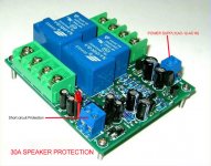
I recently purchased a speaker protection kit from ebay and of course it doesn't come with any literature so I have a question. These are the features is has;
The board include the regulator circuit of 7812, but the schematic hasn't been updated.
Fuctions:
With DC protection
Power-delay
Short-circuit overload
Fault protection alarm
I know how to hook up the speakers but I don't know how to hook up the short circuit protection circuit. hopefully one of you can help with that.
Thanks, Terry
Attachments
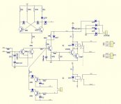
The short circuit protection goes to the emitter of one of the NPN output transistors in your amp, assuming the amp has an EF output and a small value resistor, 0.22-ohm or so, at the emitters that functions as a current sensor for a short circuit condition.
Obviously, such a protection circuit will not fire when a short circuit happens and causes a current in the PNP arm of the output stage. This can be fixed, if possible, by lifting the 5551 emitter and the 2u2 cap joints from "L-IN", "R-IN", and connecting them to the PNP output transistor emitter of the associated channel.
Obviously, such a protection circuit will not fire when a short circuit happens and causes a current in the PNP arm of the output stage. This can be fixed, if possible, by lifting the 5551 emitter and the 2u2 cap joints from "L-IN", "R-IN", and connecting them to the PNP output transistor emitter of the associated channel.
Some quick notes without a full review....
If the values are as listed on the schematic the right speaker trip value will be roughly 10X more sensitive than the left...if that's indeed how they populated the schematic.
Be careful with grounds...it's possible to create ground loops with a circuit like this.
If the values are as listed on the schematic the right speaker trip value will be roughly 10X more sensitive than the left...if that's indeed how they populated the schematic.
Be careful with grounds...it's possible to create ground loops with a circuit like this.
Looks like I should just leave the short circuit part out. As for the ground loop, the speaker ground connections just go straight through the unit. I hooked them up because I figured that the unit needed to compare the hot to the ground in order to know if there was DC on the output. I don't hear any grounding issues.
Thanks, Terry
Thanks, Terry
- Status
- This old topic is closed. If you want to reopen this topic, contact a moderator using the "Report Post" button.