> I went through the TubeCAD "SRPP Deconstructed" article, but gleaned very little practical info. I get lost in the complexity of the problems they try to solve on that site sometimes.
> B-b-b-but... i like math.
I hate math, but don't find John's derivations very daunting. You probably just need to think more about what they mean. Get your head inside the tube. Be the electron. Feel what the electron feels.
> 50+mA/V at currents around 20mA.
Do you really want 20mA? That's a lot of heat, and a lot of power supply filter.
Pick your current and voltage first. It is rare to run an audio voltage amp at more than a few mA. 20mA is starting to look like a Power amplifier, and in that function you will usually accept less voltage gain in return for better power output.
Remember that Triodes are magic because they have build-in plate-grid feedback. As soon as you cascode a triode, you lose that magic. You almost may as well use a Pentode.
> I guess current to bias voltage is an important issue too.
If you know Mu and plate voltage, you pretty-near know the bias voltage.
PRR said:> two PNP transistors make a dandy CCS plate load without heater worries.
Kewl!
And then we replace the bottom tube with an NPN. Gm at 1mA: 12AX7: 1,600uMho, 2N2222, 40,000uMho. 25 times more gain, lower cost, what's not to like?
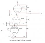
I sketched up a crazy little thang, a cascode with a triode strapped pentode in the top position. The cascode would be a triode strapped bottom tube with a grounded grid pentode on the top.
As for the transistors , already done it man... and with Jfets downstairs too, and with a mosfet ccs and a jfet bottom element with 1/2 of a 6922 in the middle. I want to see how far tubes will go. I'm tickled by this pentode idea.
Could someone tell me if I am barking up any kinda worthwile tree with this attatched schematic sketch?
Attachments
PRR said:> two PNP transistors make a dandy CCS plate load without heater worries.
Kewl!
And then we replace the bottom tube with an NPN. Gm at 1mA: 12AX7: 1,600uMho, 2N2222, 40,000uMho. 25 times more gain, lower cost, what's not to like?
What I didn't like was that with larger input signals, there was always some clipping going on. I don't make inputs for turntables, and the like. I mostly tinker with amps for CD/DVD player use and musical instrument amps. So if you are dealing with input voltages of a few volts, then there is usually some audible clipping going on there.
PRR said:
what's not to like?
The transistor used for its AC gain?
SY said:Personal opinion: transistors and the like work better in constant voltage and constant current applications. I think tubes have a much more arguable case when amplifying signal voltage or current. /personal opinion
Yeah, they do make life easier. Well, I have a bunch of MPSA56 's just hanging around, maybe I'll give 'em a whirl as the CCS. Any hot tips before I start blowing them up?
Transistors make fine sacrifices to the G.O.T.
Yup, thanks! That's my baby
An externally hosted image should be here but it was not working when we last tested it.
aletheian said:Hey, as a side note, do you run the geek zone? I saw your signature down at the bottom there. Great website.
Yup, thanks! That's my baby
Well, I decided to kick around a few tubes in this circuit. 6ha5 as the bottom element in a cascode, 6AN4 as he top, and an EF184 pentode as a current regulator up top. I'm also going to try PC900 and 6GK5 in the bottom, and I might try a 6SU7 in the grounded grid part of the cascode too.
Thanx again for all the help.
Thanx again for all the help.
> barking up any kinda worthwile tree
Output node impedance is shunted by (R5+R3)||R8. Without putting specific values in, or analyzing what happens at the (number tubes please; I'll number top-down) T2k-T3p R3 R4 node, I'll guess that gain is no more than 3 times higher than one pentode with a resistor load.
If not for that shunt, I'd say T1 needs a grid-cathode cap somewhere to hold its current more-constant.
> if you are dealing with input voltages of a few volts, then there is usually some audible clipping going on there.
Transistors don't have to clip.
And think: if you have "a few volts", and want gain more than you can get in one R-C 6AU7 stage (~400), then you have more than (few * 400) = a thousand or more volts of output swing. If you truly need such input and such gain, maybe you do need the 30,000 volt supply.
I caught a lot less flame than I expected for that 2N2222 remark. Is this the right forum section?
PRR said:> barking up any kinda worthwile tree
Output node impedance is shunted by (R5+R3)||R8. Without putting specific values in, or analyzing what happens at the (number tubes please; I'll number top-down) T2k-T3p R3 R4 node, I'll guess that gain is no more than 3 times higher than one pentode with a resistor load.
If not for that shunt, I'd say T1 needs a grid-cathode cap somewhere to hold its current more-constant.
> if you are dealing with input voltages of a few volts, then there is usually some audible clipping going on there.
Transistors don't have to clip.
And think: if you have "a few volts", and want gain more than you can get in one R-C 6AU7 stage (~400), then you have more than (few * 400) = a thousand or more volts of output swing. If you truly need such input and such gain, maybe you do need the 30,000 volt supply.
I caught a lot less flame than I expected for that 2N2222 remark. Is this the right forum section?
pfffft! I have a 30,000 volt power supply here in my pocket.
No, but seriously. I just like to take things to the extreme, and them back them off until they are useful. Crank it until it explodes... then back it off a bit right? I could cascade until the cows come home, but what's the fun in that?
Also, I started out solid state, so I want to take the all tube route
Back to basics
I think you might be going too far with the analysis etc.
In PRR's excellent first post to this thread the key was given. The gain of a cascode is APPROXIMATELY gm x RL where gm is the gm of the lower tube (device) and RL is the load resistor on the top tube anode (shunted by the load).
In simplest terms all you need to do is maximise both. If you want to get fancy then:
1) Maximise RL by using a dual PNP transistor Current Source load as per SY's suggestion.
2) Increase the current (and hence the gm) of the lower tube by adding a resistor from the lower tube anode up to the positive rail. This increases current in the lower tube while leaving the top tube alone.
As another line of investigation - also covered in PRR's post, run a single tube (Hi mu - say a 12AX7) in current starved mode for maximum gain and enhance that with SY's dual PNP current source load. This method WILL suffer bandwidth problems due to Miller capacitance.
Either method should give you more gain than you can possibly use.
Just my 2c worth - maybe worth less???
Cheers,
Ian
I caught a lot less flame than I expected for that 2N2222 remark. Is this the right forum section?
Lee deForest's house has many mansions.
Re: Back to basics
Interesting! I had never heard of that. I'll have to give it a try. How would I go about calculating it's value? nd does that effect the top tube at all, eg. heater to cathode voltage, etc.
Current starved with a CCS eh? I have done such things with resistors, but for a CCS Would I just set the CCS to a current to be regulated extremely low... like fractions of a milliamp? or do I do this in conjunction with Rk?
Thanx again for all your suggestions. I am picking up all kinds of new ideas here. You guys are the best. And thanx to Sy and PRR for knowing absolutely everything. I am trying to cram years of catch-up into as litle time as posible here.
gingertube said:
2) Increase the current (and hence the gm) of the lower tube by adding a resistor from the lower tube anode up to the positive rail. This increases current in the lower tube while leaving the top tube alone.
Interesting! I had never heard of that. I'll have to give it a try. How would I go about calculating it's value? nd does that effect the top tube at all, eg. heater to cathode voltage, etc.
gingertube said:As another line of investigation - also covered in PRR's post, run a single tube (Hi mu - say a 12AX7) in current starved mode for maximum gain and enhance that with SY's dual PNP current source load. This method WILL suffer bandwidth problems due to Miller capacitance.
Current starved with a CCS eh? I have done such things with resistors, but for a CCS Would I just set the CCS to a current to be regulated extremely low... like fractions of a milliamp? or do I do this in conjunction with Rk?
Thanx again for all your suggestions. I am picking up all kinds of new ideas here. You guys are the best. And thanx to Sy and PRR for knowing absolutely everything. I am trying to cram years of catch-up into as litle time as posible here.
> Increase the current (and hence the gm) of the lower tube by adding a resistor from the lower tube anode up to the positive rail. This increases current in the lower tube while leaving the top tube alone.
In rational design, this does little good. Yes, Gm increases with current, but the increased signal current from the higher Gm splits between the upper tube and the bypass resistor. If upper tube Rk is lower than the bypass resistor, then I suppose most signal current flows to the upper tube. But if you also increase upper tube plate load to very high impedance, and upper tube Mu is not very-very high, its Rk will be quite high (about (R+Rp)/Mu or so). And we usually want good output current to drive a load and/or stray capacitance.
In irrational design, with kilovolt supply or very high Z current regulators everywhere, I dunno. All the easy assumptions fly in the face of electronic reality. "Infinite" impedances never turn out to be as infinite as you hoped.
There's a reason most Classic tube design can be understood at a glance. It Works. Anything tricky usually does not work any better than the same number of parts laid out simply.
I assume you have chewed the Tube Op-Amp thread SY started. I haven't; I caught the tail of that era and don't remember it fondly. But Julie (link, link) and others were getting gains of 20,000+ in compact little modules without any coupling/bypass caps. There's trickery in that, but nothing like this cascoded CCS-ed bleeder plan. Remember, when Julie started there was a war on, opamps aimed anti-aircraft guns faster than humans, and heroically complicated designs were justifiable and even built.
PRR you are a gentleman and a scholar, and a wealth of information.
In the next week I'll be breadboarding what I see as the most extreme, but still useable variation. Just a simple 2 triode cascode in the bottom with an EF184 pentode CCS on top of it. I'm interested to see how my math will hold up in the real world. Everything is snubbered and bypassed at first with grid stoppers on every grid. That's going to be my test bed. I'm starting out with 7-pin VHF/RF tubes, and I'll move on to high GM russian tubes and the like if things look good.
Thanx again.
- Status
- This old topic is closed. If you want to reopen this topic, contact a moderator using the "Report Post" button.
- Home
- Amplifiers
- Tubes / Valves
- Question about single NOS triodes in cascode for fun