I did build a single channel. 
I can report it worked well. I need to get my PC FFT working so I can at least get some basic measurements. But it seemed to sound fine to me.
If there is interest I will get around to designing a proper PCB for it.
I actually used a bipolar PNP for the phase splitter, but really only because I was low on IRF9610s. And only used a single pair of IRFP140s for the heavy lifting.
I will build a stereo amp as soon as I am able.
Cheers!
Russ
Hi Alex,
Earlier in the thread you suggested you might elaborate on the implemention of your interesting 'minimalist' circuit design..
"There are limitations and quirks in this circuit - I hope I know most of these and know how to overcome them. Perhaps I should do a brief note on the basic requirements, dangers and solutions in this circuit."
- Alex
I for one would appreciate any further notes you might add regarding the "real-world" application of you amplifier...
Thanks if you have time.
Russ White said:I did build a single channel.
I can report it worked well. I need to get my PC FFT working so I can at least get some basic measurements. But it seemed to sound fine to me.
If there is interest I will get around to designing a proper PCB for it.
I actually used a bipolar PNP for the phase splitter, but really only because I was low on IRF9610s. And only used a single pair of IRFP140s for the heavy lifting.
I will build a stereo amp as soon as I am able.
Cheers!
Russ
Mr Russ,
Any updates on your X-Pro based NQCA.....
Kanwar
Workhorse said:
Mr Russ,
Any updates on your X-Pro based NQCA.....
Kanwar
I can only report that I have tested a pair of amps based on this design, and they sound very good. I cannot adequately measure them yet, but they are stable with no detectable white noise/hiss. I cannot hear any nasty crossover distortion as I have with some other FET amps with low bias current.
My measured bias is < 70ma
I will later try a more powerful amp with better PCBs.
Cheers!
Russ
I am sure I will. The version I built used only two N-Channel FETs as X-pros did, and is probably good for around 50W.
It been a few months since I even looked at it, I will see if I can dig them up.
I used IRFP140s for the power transistors.
I used both BJT and IRF9610 for the phase splitter.
Cheers!
Russ
It been a few months since I even looked at it, I will see if I can dig them up.
I used IRFP140s for the power transistors.
I used both BJT and IRF9610 for the phase splitter.
Cheers!
Russ
X-pro's Quasi or "current sharing" is circlotron (almost)
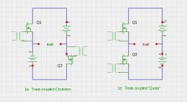
I am not sure whether this should be the start of a new thread or not, but I will propose that the output topology used by X-Pro in the Creek amps (5350 4330) are essentially equivalent to a the output topology of the Circlotron (aka. floating bridge). The main different is in the phase splitter. If the output stage gates of both topologies are driven transformer coupled, then they are equivalent except for various parasitic elements that are never modelled in Spice simulations.
(This is my first attempt to insert image attachments in a forum message, so I apologize for some likely formatting problems.)
Figures 1a and 1b illustrate the topologies. Their only difference is the order of the power supply in the two current loops. With the transformer coupling, this ordering is irrelevant.

Usually we want to avoid transformer coupling (and sometimes avoid capacitor coupling too). Therefore we must have drive circuits for gates of the output FETS which have low distortion properties.
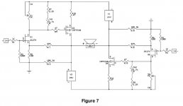
Michael Rothacher's paper "Build the the Amazing FET Circlotron"
http://www.passdiy.com/pdf/Build The Amazing FET Circlotron.pdf
Below is Figure 7 from that paper showing the totally symmetric (identical) drive circuits for the two output FETS. This cct requires balanced inputs, which will usually necessitate a proceeding phase splitter stage, thus creating an assymetry in the overall cct.

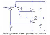
Alex Nikitin's paper "N-channel D-MOSFET output stage with improved linearity" http://www.ant-audio.co.uk/Theory/N-channel D-MOSFET output stage with improved linearity.pdf shows a Quasi (or as Alex prefers) "current sharing" output stage with several different optimizations of the driver stage. Here is the variant that is used in the Creek 5350:

My claim is that the two topologies are nearly identical, except for the phase splitter parts of the circuits. If the phase splitters can be designed to minimize distortion (and other potential problems), then there should be no difference in the performance of the two topologies.
I am not sure whether this should be the start of a new thread or not, but I will propose that the output topology used by X-Pro in the Creek amps (5350 4330) are essentially equivalent to a the output topology of the Circlotron (aka. floating bridge). The main different is in the phase splitter. If the output stage gates of both topologies are driven transformer coupled, then they are equivalent except for various parasitic elements that are never modelled in Spice simulations.
(This is my first attempt to insert image attachments in a forum message, so I apologize for some likely formatting problems.)
Figures 1a and 1b illustrate the topologies. Their only difference is the order of the power supply in the two current loops. With the transformer coupling, this ordering is irrelevant.

Usually we want to avoid transformer coupling (and sometimes avoid capacitor coupling too). Therefore we must have drive circuits for gates of the output FETS which have low distortion properties.
Michael Rothacher's paper "Build the the Amazing FET Circlotron"
http://www.passdiy.com/pdf/Build The Amazing FET Circlotron.pdf
Below is Figure 7 from that paper showing the totally symmetric (identical) drive circuits for the two output FETS. This cct requires balanced inputs, which will usually necessitate a proceeding phase splitter stage, thus creating an assymetry in the overall cct.

Alex Nikitin's paper "N-channel D-MOSFET output stage with improved linearity" http://www.ant-audio.co.uk/Theory/N-channel D-MOSFET output stage with improved linearity.pdf shows a Quasi (or as Alex prefers) "current sharing" output stage with several different optimizations of the driver stage. Here is the variant that is used in the Creek 5350:

My claim is that the two topologies are nearly identical, except for the phase splitter parts of the circuits. If the phase splitters can be designed to minimize distortion (and other potential problems), then there should be no difference in the performance of the two topologies.
Alex,
After going through the topic in more depth. I agree with you that non-complementary and Quasi-complementary have substantial difference in way of their working and emulating reflected impedances at output. Thanxz for teaching me with nice explanations and clearing my ignorance.
After going through the topic in more depth. I agree with you that non-complementary and Quasi-complementary have substantial difference in way of their working and emulating reflected impedances at output. Thanxz for teaching me with nice explanations and clearing my ignorance.
Kanwar,
By ending up with different output impedances from each half, you force higher levels of H2 and H4. Put another way, this sounds a bit more warm.
Some people actually prefer a quasi amp over a complementary output stage.
But then you knew this already.....
Ciao
Hugh
By ending up with different output impedances from each half, you force higher levels of H2 and H4. Put another way, this sounds a bit more warm.
Some people actually prefer a quasi amp over a complementary output stage.
But then you knew this already.....
Ciao
Hugh
Kanwar,
By ending up with different output impedances from each half, you force higher levels of H2 and H4. Put another way, this sounds a bit more warm.
Some people actually prefer a quasi amp over a complementary output stage.
But then you knew this already.....
Ciao
Hugh
Hello Hugh,
Long time no see ,
I tend to differ here, in the above examples given by Alex, the output impedances are highly balanced if compared to the usual quasi-complementary, because of the feedback. Also if the outputs are configured as VCCS then also you will have balanced case of impedences.
Correct me if i am wrong, but after having simulated the VCCS stage[my own version] in open loop, i am not getting H2 which is higher than H3.
post12.
What is the difference between "current sharing" and Quasi complementary?
In the current sharing figure: The Drain of Lower output mosfet makes connection with the Source of P-channel input driver mosfet, which in a way provides local negative feedback and linearizes the full output stage.
Cheers,
Kanwar
Last edited:
- Status
- This old topic is closed. If you want to reopen this topic, contact a moderator using the "Report Post" button.
- Home
- Amplifiers
- Solid State
- Quasi or not Quasi - that is the question