Bingo. A coupling cap (assuming that the time constant with the input resistance is reasonably high) has negligible voltage across it so cannot cause distortion. And actual experiment bears this out.
SY, how does this reflect when applied to a coupling cap in a VT output stage? Normally there is about 200 volts DC difference between the driver stage and the output stage which is overcome by the coupling cap. Is this a situation where the cap would be capable of adding distortion?
The capacitor will have a substantial DC voltage across it.
If the capacitor value is chosen to pass the signal then it will have near zero signal (AC voltage) across it.
If there is no AC voltage, there is no AC distortion.
If there is near zero AC voltage then there is near zero distortion.
If the capacitor value is chosen to pass the signal then it will have near zero signal (AC voltage) across it.
If there is no AC voltage, there is no AC distortion.
If there is near zero AC voltage then there is near zero distortion.
The capacitor will have a substantial DC voltage across it.
If the capacitor value is chosen to pass the signal then it will have near zero signal (AC voltage) across it.
If there is no AC voltage, there is no AC distortion.
If there is near zero AC voltage then there is near zero distortion.
Ok, so a properly designed AC coupled amplifier should sound exactly the same as a DC coupled amplifier (given that their layout, topologies, parts and operating points are the same)?
SY, how does this reflect when applied to a coupling cap in a VT output stage? Normally there is about 200 volts DC difference between the driver stage and the output stage which is overcome by the coupling cap. Is this a situation where the cap would be capable of adding distortion?
No, that's DC voltage, not AC voltage (i.e., signal).
No, that's DC voltage, not AC voltage (i.e., signal).
Very interesting. If interstage capacitor distortion depends on AC voltage difference over the capacitor does that also mean that when using different capacitors of the same value there cannot be a difference in distortion?
Different caps of the same value will have the same AC voltage across them. The distortion generated by this will depend on the cap characteristics, but unless poorly chosen will be very small. People who want to sell you expensive caps, or conversely wish to brag about the expensive caps they have been persuaded to buy (or seek affirmation of their decision to buy), seem unable to grasp this point.
The impedance of a 10u cap is about 15 ohms at 1kHz. Let's say you have a 50k load and this is an egregiously bad capacitor (10% distortion, i.e., variation in impedance with voltage). The distortion that's passed along is then about (0.1)(15)/50000 times 100 to make it a percentage. That's 0.003%. Now, the distortion of even inexpensive electrolytics is an order of magnitude better, so really it's only bass distortion that could potentially be an issue. And even that is extremely low, as a few minutes doing a loopback with a soundcard (which uses electrolytics) will quickly demonstrate.
This is why you have to think through how a cap is used rather than applying measurements made with very different signal level and currents. For example, DA is important if you're using a cap for a timing circuit or integrator. It's not important at all for AC signal. ESR is critical for power supply caps, but unimportant for coupling. And so on.
This is why you have to think through how a cap is used rather than applying measurements made with very different signal level and currents. For example, DA is important if you're using a cap for a timing circuit or integrator. It's not important at all for AC signal. ESR is critical for power supply caps, but unimportant for coupling. And so on.
...and then, there is microphony.
At the input of my Linear Audio low noise preamp there is a film capacitor. It has some DC bias across it. The input impedance of the preamp is very high.
Tapping on the box will give nice output voltage swings, very large pulses.
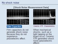
All capacitors are microphonic to a degree. For film caps, vibration causes a change in capacitance as the armatures move. The consequences are proportional to capacitor bias voltage and circuit impedance. Without voltage, there is no effect. At low circuit impedances, the voltage produced is very small. I guess this could explain nicely why tube guys (high bias voltage, high impedances) care so much about boutique caps whereas solid state amp guys (no bias, low impedances) don't seem to care that much.
High-K ceramics like X7R are piezoelectric, which is another can of worms. They also have the worst dC/dV of all. No-one in their right mind would use X7R ceramic capacitors as coupling caps, or to decouple or filter a high impedance node, like a voltage reference or the noise filter pin on an LDO... for example...
NP0 on the other hand is perfect.
Of course, the same applies to cables. If I connect a nice BNC 50 ohms cable to the input and twist it around, all sorts of stuff happen...
At the input of my Linear Audio low noise preamp there is a film capacitor. It has some DC bias across it. The input impedance of the preamp is very high.
Tapping on the box will give nice output voltage swings, very large pulses.
All capacitors are microphonic to a degree. For film caps, vibration causes a change in capacitance as the armatures move. The consequences are proportional to capacitor bias voltage and circuit impedance. Without voltage, there is no effect. At low circuit impedances, the voltage produced is very small. I guess this could explain nicely why tube guys (high bias voltage, high impedances) care so much about boutique caps whereas solid state amp guys (no bias, low impedances) don't seem to care that much.
High-K ceramics like X7R are piezoelectric, which is another can of worms. They also have the worst dC/dV of all. No-one in their right mind would use X7R ceramic capacitors as coupling caps, or to decouple or filter a high impedance node, like a voltage reference or the noise filter pin on an LDO... for example...
NP0 on the other hand is perfect.
Of course, the same applies to cables. If I connect a nice BNC 50 ohms cable to the input and twist it around, all sorts of stuff happen...
Ah gee .....
this is what I was trying to avoid in this thread - but there, it is out now. As SY, Andrew and others have said multiple times. I apologise to have sidelined the thread onto this OFTEN misunderstood side-track, something which in the past and elsewhere has lead to almost as much strife as cables (OOPS!). Perhaps to wait for another thread on this as I was going to??
But Peufeu,
Capacitors can be checked for microphonics. Again, please, not to open another argument; I am simply observing the courtesy of replying to you.
It is easy to check capacitors for microphony. Simply connect one per leads away from unrigid pc boards, apply the suspect conditions or any test condition, and apply a blow, or rather a tap - do note that a direct tap will have a force orders larger than microphonics through air. You will find that a fair blow will be required to elicit any ill effect - at least in the cases I have tried (I do not know what manner of crap capacitors can creep onto the marketplace - anything is possible these days, perhaps more so with flat caps). I would assume it would otherwise be rather difficult to isolate capacitor microphonics per se from other possible microphonic effects in a pc board set-up in an enclosure. Perhaps that was what you may have observed?
One such possible disturbance generated in particularly screened cables is called the 'tribo-electric' effect. Other than cause a minute change in capacitance, a tiny voltage is generated, which normally overrides the momentary capacitance change. (This principle is often used to detect road wheels going over a cable on a road.)
An interstage coupling transformer (IT) does not block DC.
this one does....ultrapath line preamp....
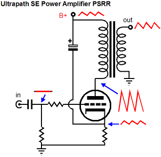
Now that you have an example, explain how the transformer blocks the DC.
And how does it avoid using A DC blocking capacitor?
this is what I was trying to avoid in this thread
Why ? it is a thread about coupling caps...
But Peufeu,
Capacitors can be checked for microphonics. Again, please, not to open another argument; I am simply observing the courtesy of replying to you.
Yeah and it is not difficult, put known DC bias on it, through known (high value) resistor, tap on it, measure voltage spike, you get dC/dFingertap. Getting good reproductibility of the "tap" may be not so easy...
If R>100k, it is very easy to see. With R=50 ohm, good luck.
do note that a direct tap will have a force orders larger than microphonics through air.
Board flexing is the main factor... which is why you see damped chassis, anti-vibration spiky feet and all sorts of stuff...
With SMD caps it is the only factor (and it does not need to be large).
One such possible disturbance generated in particularly screened cables is called the 'tribo-electric' effect. Other than cause a minute change in capacitance, a tiny voltage is generated, which normally overrides the momentary capacitance change
Yeah, quite spectacular across 1 MOhm scope input impedance... not if the cable is driven by a low-Z source like an opamp,
Now that you have an example, explain how the transformer blocks the DC.
that is for you to find out......
")
Why ? it is a thread about coupling caps...
Yeah and it is not difficult, put known DC bias on it, through known (high value) resistor, tap on it, measure voltage spike, you get dC/dFingertap. Getting good reproductibility of the "tap" may be not so easy...
If R>100k, it is very easy to see. With R=50 ohm, good luck.
Board flexing is the main factor... which is why you see damped chassis, anti-vibration spiky feet and all sorts of stuff...
With SMD caps it is the only factor (and it does not need to be large).
Yeah, quite spectacular across 1 MOhm scope input impedance... not if the cable is driven by a low-Z source like an opamp,
Yet ceramics (X7R, X8R, X8L) are used on PCB's (not for coupling) that have to work in high vibration situations, and where they are tested under vibration. Tapping a capacitor has no relevance to real world operating conditions. These PCBs are used in critical situations where vibration greater than you will encounter in the domestic environment, and standard vibration testing shows that the fears over these caps is misplaced. The only test that will show the extreme effect of the fingernail tap is the ballistic test, never gonna be encountered in the domestic environment.
So X7R etc. MLCC can be used and are used in certain circuit position with no problems or vibration issues, even LDO outputs....
Send your opinion to Panasonic
Attachments
Last edited:
Read what I said carefully, I have already covered this, shock testing, IN THE REAL WORLD DOING VIBRATION TESTING WE COULD ONLY REPLICATE THE FINGER NAIL TAPPING WITH A BALISTIC TEST.
So under normal operating conditions in a domestic/industrial environment you will not generate these forces.
This is not an opinion it is from empirical data working on certain projects where vibration testing is carried out so that you can be sure the equipment works under high vibration.
I cant understand why you bothered posting, how often do you go round your equipment when it is playing tapping capacitors with your finger, like all things there are extremes that aint gonna happen in your living room?
Last edited:
I don't need to "find out".that is for you to find out......
I can see you were wrong on both counts and your example does not support your contention that DC blocking capacitor can be replaced by no cap. Remember I said
and you followed up withIn the situation of a DC blocking capacitor, the best capacitor can NEVER be no capacitor.
unless you use an IT or servos...
If your example is examined you will see that the circuit REQUIRES DC current to flow from the PSU to the valve. A resistor load or an inductive load can be used.
If a DC blocking capacitor is inserted instead the example circuit stops working.
It needs a load that PASSES DC, not a DC blocking capacitor.
I have twice offered you the opportunity to explain
What is an IT?
And how does it avoid using A DC blocking capacitor?
An interstage coupling transformer (IT) does not block DC.
Quote:
And how does it avoid using A DC blocking capacitor?
Why are you being so unhelpful?
Last edited:
MLCC can be used and are used in certain circuit position with no problems or vibration issues, even LDO outputs....
Sure !
The output of a LDO with some minimum load is low-impedance, so the capacitors can get piezoelectric and dump some charge into it, the LDO is going to do its job.
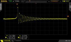
I've found a nicer way to generate some vibrations... there is a 330 ohm thru-hole load resistor on the board, with long legs, so I pluck it with my fingernail and it goes "twangggg" like a little guitar string. It is much less "violent" than tapping.
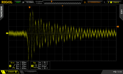
First trace is LDO powered off, output cap (10µ X7R) produces ~200µV into 330R load when twanggged, so the piezo current here is < 1 µA. Nothing really scary...
Second trace is when the LDO is powered on, the output moves 1.5 mV pk-pk here, that's a lot more ! It is because the LDO's reference bypass / noise reduction pin is bypassed by a 10nF X7R capacitor. When this one gets microphonic, it injects current into a very high impedance node (VREF), which gives much more interesting output.
If I replace this 10nF X7R cap with a C0G cap, no more problems. The LDO reference is clean, and it has no problems controlling the output, so I won't post a trace, there is nothing to see.
What I meant is that
- since capacitor microphony results in a current, it only matters in high impedance circuit nodes.
- leaving aside piezoelectric caps, for film caps this current is also proportional to voltage across capacitor, so if there is no voltage across it (or just a few mV of DC offset we want to get rid of), there is no problem... microphony would be a problem for tube amps with high DC biases and high impedances.
- if you got a CCS whose output enters the main signal path, or similar, don't bypass its reference with high-K dielectric ceramics
Attachments
Last edited:
- Status
- This old topic is closed. If you want to reopen this topic, contact a moderator using the "Report Post" button.
- Home
- Member Areas
- The Lounge
- Quality Input Cap