Gentlemen,
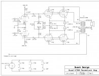
Your help and experience would be greatly appreciated. I've just completed the first of 2 quad KT88 based amplifiers, and I'm unable to surpress a very persistant self-oscillation (with no input to the grids). The circuit utilizes 4 KT88s (Electro Harmonix) in a push-pull parallel, ultra linear configuration (biased for class AB1, but adjustable) with 6SN7s drivers, preamp and phase inverters. The output transformer is a Hammond 1650W (1.9K CT pri.). The power supplies are all choke-input. The B+ supply for the finals is 570 VDC with 2 LC sections (10H chokes and 220 UFD caps) in the filter. The supply is very"stiff" and will easily supply 600 ma with less than 15 V droop. Ripple is <.01% RMS with a full load. B+ for the drivers, preamp and phase inverters is 220 VDC with a single LC section (7H + 440 UFD) which will supply 100 ma with <.01% RMS ripple. The bias supply provides -90VDC again with a single LC filter (25H + 440 UFD) and is adjustable for each pair of tubes. The filaments are run on clean DC as well.
Here's the problem: with no drive (coupling caps from the drivers completely disconnected) and using just 2 tubes in the circuit, it is completely stable at any idling current (typically ~ 30ma / tube, but values from 0 to 100ma are completely solid). If you add the second pair of parallel tubes and increase the idle current to anything over ~20 ma/ tube, the circuit immediately goes into oscillation at approximately 60 Khz. All the tubes appear to be good (any 2 of the 4 will work fine and exhibit similar transfer characteristics). Lead dress is not a problem, the output is driving a solid 4 ohm, 400W, non-inductive load, all the supplies are well-bypassed, and the oscillation is not originating in the drivers. Does anyone have any ideas?
All help would be greatly appreciated,
Chris
Attachments
Hi Chris,
The first thing I would do is to carefully verify the color coding on the output transformer primary windings by checking the DC resistance and their relationship to each other. If this pans out OK, you may need some stopper resistors for the KT88's. You may or may not need all of these typical values mounted right at the sockets. ½ or 1 watt carbon comps or film.
1000 ohms for the control grids.
470 ohms for the screens.
10 or 20 ohms in the plates.
Hi Chris,
You will probably need grid stoppers at pin 5. You may also need to put a resistor in series with the UL tap and each screen. 100 to 470R should do it. You might also try a 1k resistor in series with about a 100pf cap between the screen and the plate taps on the transformer - both phases.
You will probably need grid stoppers at pin 5. You may also need to put a resistor in series with the UL tap and each screen. 100 to 470R should do it. You might also try a 1k resistor in series with about a 100pf cap between the screen and the plate taps on the transformer - both phases.
You might find the screen grids are the culprit here, and I recommend around 100 ohms directly at each screen grid. (pin4)
The only other concern would be if there was enough phase shift in the primary at 60kHz to allow the amplifier to oscillate.
I have had similar problems in the past and I usually found that there was a vhf oscillation at the root of it all, and it was due to feedback at the screens, if this is the case the resistors should take care of it.
Stoppers on the grids are highly recommended and something in the range of 1K - 10K is typical. I tend to favor values around 1K. Again must be installed right at pin 5 as previously mentioned.
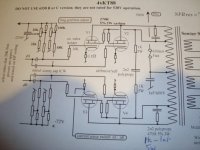
Chris; that circuit is a very poor design, I suspect the previous stages are so slew-rate slugged that the audio response is poor to avoid the output stage oscillating. There are no grid stoppers in the screen grid circuits, and the design with KT88's (high gm tubes) will guarantee to oscillate at the leakage resonant freq of the o/p tranny. I've enclosed a sim design with tamed output stage with sim power. Note; 570V B+ and an wild oscillating primary is mighty dangerous stuff, and inadequately rated components will simply puff up. One is up against the leakage/reactive components of the o/p tranny, and snubbing sim to that in the pic enclosed sorted my problem out. The screen to screen is a drastic measure, this highlights the inherent leakage inductance between these taps when compared to primary as the transformer size increases.
I presume you are using 40% UL taps. In reality I used 5-7W series snubber resistors (not wire wound) and min 1kV rated polypropy caps. Considerable amount of power is dissipated in the snubbers so be careful doing 5-10Khz square wave tests at power.This is to be taken seriously.
KT88's are becoming expensive and every method should be used to protect them, a low wattage screen resistor will do alot. Note 630mA fuse used in CT in pic. You haven't given a layout ? This will also play a big part.
Attempting to tame a wild rat isn't easy. Good luck
richy
Attachments
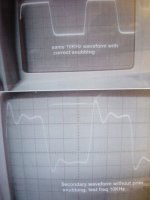
A pic of some output stage waveform differences. Poorish bild quality but they illustrate before and after.
I wonder how many tube amps look like this ? The poor quality lower waveform goes into oscillation with a LS crossover .. The output stage with the upper snubbered square wave can take another 20dB global nfb before instability occurs. This won't be in every case and depends on tap and quality of o/p tranny.
richy
Attachments
Thank you all for the help.
Success (and very cautious optimism). Added the 1K stops at each of the control grids and the 470s at the screens as suggested. Not only is it now stable, but a cursery look at the output waveform (with a sine wave input) is surprisingly good with zero NF (other than the inherent NF from the untralinear configuration). I'm sure I'm in for lots more tuning once I look at the square wave response and the THD/IM numbers, but for now, it's stable enough to develop further which is great.
One last question: what have you found to be the optimum idle current for a KT88 in fixed bias, ultralinear P-P configuration running AB1 with 550-570V on the plates? The data sheets are all over the place from 30 ma. to 90 ma.
Cheers,
Chris
chris.busch said:One last question: what have you found to be the optimum idle current for a KT88 in fixed bias, ultralinear P-P configuration running AB1 with 550-570V on the plates? The data sheets are all over the place from 30 ma. to 90 ma. Cheers,
Chris
I've always found that 60mA was a good compromise between efficiency, heat, tube life and good sound. I run GE (JAN) 6550A's in UL at 60mA each with 600 volts. KT88's are virtually the same.
Oops - coming in completely late, and with experts having already solved your problem (glad for you; as Rich mentioned, oscillation in a high-voltage high-power amplifier is NOT to be played with).
I just noticed that your first experience was "with coupling caps completely disconnected". That would mean G1 stoppers of 47K+ in the circuit, as there was no feeding low-Z device. Good to start with in such cases, but rather with the coupling caps connected to common. One would also need to be cautious when connecting NFB round the final circuit, perhaps starting with a low amount and keeping a check all the time with a square wave and scope while increasing NFB (not knowing if any is going to be used).
I am sorry - obviously (I am bold to say) there would have been oscillation in that set-up. As Rich mentioned the design (and it is always easy to criticise), but I also frown on feeding power tubes from a driver with 47K loads into 47K next-stage grids. The load line would not be encouraging for low distortion, etc.
But enough. We all have our favourite topologies. This might work out all right.
To all:
I might need to apologise here.
I inserted a critical remark about the designer of the circuit in the previous post, and only noticed after I pushed the send button that it was Chris himself. I then deleted the remark, but some may have read it.
I reacted under the impression that this was a published commercial or at least tested design, in which case one would have thought that the designer would have sorted out the problems experienced by Chris. I only now noticed it was his own beginning to try something himself, which is a completely different state of affairs!
I should have first had my cup of coffee. Chris, I apologise, and do wish you every success with this. Rest assured that I (supposed to be a veteran), have committed follies and still do that I would not dare commit to paper!
Regards
HINT: Not because I don't like BIG BANGS; but my bench approach for working on this types of power amp is to setup a AC line variac to- AC line isolating transformer and connect a discrete rectifier and initially work with a much lower B+ with a fuse or light bulb in series. Obviously you will have to fire up the heaters and the negative grid bias with existing amp tranny at the normal AC line voltage from another AC source.  Make darned sure you fire up the negative and heaters first. Got the jist ?
This is my standard procedure prior to low level square wave testing and/without global nfb. Checking the amp with sinewave without the global nfb loop is fine but not very informative.....BUT everything can change when this is connected or may oscillate with an LS and not dummy load. If you haven't got a 4/8 Ohm dummy load at the amp rating make one or get one.
My tried and tested approach is to initially use a lower B+ for the output stage til one is assurred that circuit is working and any oscillation isn't going to damage components. An ultrasonic screen grid oscillation can instantly damage resistors without discolouration nor smell.
The square wave business will show up everything and we can follow through the problems when the squarewave is applied.
With some tubes e.g Svetlana 88's, 60mA quiesent at 530V is beginning to get the anode glowing. Others can behave differently. As Hollowstate mentions, a 6550A is a darned good competitor, (I.M.O it is a better tube than an 88) but I would question this rating for recently made types. (Svet 6550C B+=470V MAX in UL ?)
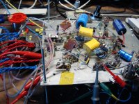
I hope your amp isn't like the pic.
richy
$
---------QUALITÄT LIEGT IN UNSERER NATURE--------
Make darned sure you fire up the negative and heaters first. Got the jist ? This is my standard procedure prior to low level square wave testing and/without global nfb. Checking the amp with sinewave without the global nfb loop is fine but not very informative.....BUT everything can change when this is connected or may oscillate with an LS and not dummy load. If you haven't got a 4/8 Ohm dummy load at the amp rating make one or get one.
My tried and tested approach is to initially use a lower B+ for the output stage til one is assurred that circuit is working and any oscillation isn't going to damage components. An ultrasonic screen grid oscillation can instantly damage resistors without discolouration nor smell.
The square wave business will show up everything and we can follow through the problems when the squarewave is applied.
With some tubes e.g Svetlana 88's, 60mA quiesent at 530V is beginning to get the anode glowing. Others can behave differently. As Hollowstate mentions, a 6550A is a darned good competitor, (I.M.O it is a better tube than an 88) but I would question this rating for recently made types. (Svet 6550C B+=470V MAX in UL ?)
I hope your amp isn't like the pic.
richy
$
---------QUALITÄT LIEGT IN UNSERER NATURE--------
Attachments
Thanks to everyone for the help. The result is surprisingly good - I've been listening to very demanding music for the last hour (the ultimate test), and given what I've heard, I'm starting the second monoblock today.
Square wave response is excellent with no NF other than that inherent in the U-L design. I can optimize THD down to about 1.3% across the audio range and at most power levels up to a bit over 100 W into 4 ohms. Although the schematic showed 6SN7 drivers, I'm actually driving the KT88s with a 6BX7 driver stage that was left over from my last amp (push-pull 3-500Zs - failure - completely impractical). It may not the best choice for the KT88s, but it does have a low output impedance and will drive almost anything. Before I build the second amp, I'm going to do some further development work on the driver and preamp/phase inverter stages. I suppose that I'll also have to construct another PS as well, since I'm seeing >500ma plate current on peaks, and while this supply is comfortable with that, I'm not sure it will be supply 2X that for both channels at low ripple. That's physically painful, as there are almost 60 lbs of magnetics in the PS alone.
Again, my appreciation - the final schematic will be available to anyone who's interested.
Chris
Hi Johan,
No need to appologize for any critical remarks - that what I was seeking - constructive criticism and colaboration. It's all good advice and I appreciate you taking your time to reply. Regarding the load impedance for the drivers, you're exactly right - just an autocad mistake - those would be wimpy drivers indeed! The correct plate and cathode load resistor value for the 6BX7s that I'm using is 3.3K - I need to correct the schematic.
My background is HF and VHF high power tube amps, so I always bring up new PS circuits with a Variac (I've picked too many pieces of electrolytic caps out of my beard) - that's really good advice. As you can see from my initial lack of grid and screen stoppers, I'm an amateur at audio amp design - I've been working with zero-bias triodes too long!
I also absolutely agree that sine wave testing doesn't show much - nothing like a square wave to illuminate your sins. I'm driving the input with a Tektronix PG508 pulse generator for the sq. wave testing and a Tek SG505 for the sine wave (it's the cleanest analog source that I know of) the load is 4 ohm, 400w. non-inductive. I sample the output with both voltage and current probes and digitize it with an HP 54501 and measure THD with both a Tek AA5001 distortion analyzer and a PC-based FFT analyzer. Lot's more testing (and development and fun) to do, but for right now, actually hearing it produce listenable sound is a real victory.
Cheers,
Chris
- Status
- This old topic is closed. If you want to reopen this topic, contact a moderator using the "Report Post" button.
- Home
- Amplifiers
- Tubes / Valves
- Quad KT88 oscillation problem