I am seeing a few people using LM type chips in the front end of a differential pair, which is in my opinion is just not adequate for the intended job. I think they are adequate for under output tubes - but simply do not have a linear or high enough impedance for the critical input stage. The signal will fall out of balance above about 10khz producing all sorts of nasty harmonic distortions.
Its so simple to build a two transistor CCS for this application that it's just criminal to use a LM chip.
Shoog
Its so simple to build a two transistor CCS for this application that it's just criminal to use a LM chip.
Shoog
Its so simple to build a two transistor CCS for this application that it's just criminal to use a LM chip.
Shoog
My general question on CCS, while currently I do not have any practicable & else experiences on this. What is the benefit (THD or else) to have a CCS compared to resistor based. May the result is may also tube depended?
Hp
The stiffer the tail the better the phase balance. Effectively you are forcing the LTP to send all the signal between the cathodes, which acts as an input just like g1, The stiffer the tail the more perfect the signal transference between input valves. So the tail has to be many time higher impedance than the the valve impedance - and it is very easy to achieve with a two transistor current source. Using a resistor which is difficult to make many times higher than the valve impedance means that a substantial part of the signal can bleed away to earth via the tail.
If, as in this case, the two inputs are been driven - having a stiff tail forces the input stage to integrate any difference between the inputs.
Its a simple matter of if you are going to use a LTP - you might as well do it properly and use as stiff a tail load as possible. LM chips have a reducing impedance above about 10khz which not only makes them a poor tail load above these frequences - but also makes in a variable load with frequency.
Shoog
Last edited:
I can correct the tail problems later and I have thought about that.
What I am asking in the interm is how do you apply the feedback?
Use exactly the same cathode resistors you had originally but simply reference them to your CCS common node rather than ground. This may require another -B to give the CCS room to function.
Shoog
Sounds excellent") .
.
The suggestion about combining your two bias arrangements should work - but it will probably alter the feedback and I wouldn't like to hazard a guess at how to calculate it. It maybe a matter of experimentation with a pot to see what actually sounds best.
Shoog
.The suggestion about combining your two bias arrangements should work - but it will probably alter the feedback and I wouldn't like to hazard a guess at how to calculate it. It maybe a matter of experimentation with a pot to see what actually sounds best.
Shoog
I added on the transformer but I have a few questions regarding the impedance and the DC resistance of the coils.
I looked up the specs on the Jensen transformer and found:
- Input impedance (primary) at 1k = 14.1k.
- DC resistance of primary = 2.26k ohms.
- DC resistance of secondary = 1.9k.
The source driving the transformer will be a floating differential signal. I am a bit confused on how to configure the setup to make the input impedance 100k ohms. Should I just put a 47k ohm in series with the + and - inputs and the transformer winding? Should I tie anything to ground here?
Attachments
You cannot realistically get an input transformer to give more than its rated impedance and it will have an optimal loading impedance which will prevent it from ringing. Basically whatever that loading is you are advised to apply to the secondary and that will help to define the actual impedance of the transformer - which will be somewhat no linear with frequency.
R93 & R94 are no longer defining the input impedance. Are you certain that you will be using a none centertapped input transformer - a CT one would work better.
None of this really matters to the circuit as any self respecting preamp will be able to drive an input impedance down to 10kohms and so you need to just use what is prescribed for the transformer.
As for DC impedance - this is not really relevant unless you are passing DC through the transformer - it should not effect the transformer ratio.
--------------------
As for your feedback arrangement. You have gone from a relatively straightforward ratio to ground, to a situation where the ground leg is through the other half of the differential pair cascade. This will have increased the impedance to ground many times over - so the first thing that you need to do is define the impedance up through the differential partner and back to the power supply. What might complicate the matter even more is that this impedance will probably vary with signal.
Shoog
Last edited:
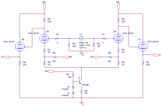
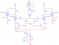
New Driver
I am looking into making a new driver circuit as part of a second revision for my current KT88 PPP amplifier. I though about Morgan Jones's book and about how he stresses there should be only a single capacitive coupled stage in the whole amplifier. I remember him saying this mainly eliminates low frequency instability.
I designed a new driver with two direct coupled differential stages that capacitive couple to the output stage. Will this, plus the fact my new circuit is simpler, help improve natural stability, even for high frequencies? Will I still need step networks and the local feedback loop Waveborn suggested I install in my old design? Overall I am trying to eliminate the need for some of that extra stability circuitry, as it has some side unwanted effects.
Overall, I learned alot but I still am far from being an expert on the stability issue.
Attachments
Last edited:
Removing coupling caps may help LF stability, but won't help HF stability. You may still need HF compensation networks. To a first approximation, LF and HF stability for a typical amp are unrelated. The best way to help loop stability (apart from understanding it) is to have a very high performance OPT.
An amplifier loop with just two LF poles (e.g. coupling cap, plus OPT) cannot oscillate, but it can still produce an LF peak so you still need to get the design right. Introducing a third LF pole, like many amps, does not suddenly turn a good circuit into a bad one. It just needs more careful design.
An amplifier loop with just two LF poles (e.g. coupling cap, plus OPT) cannot oscillate, but it can still produce an LF peak so you still need to get the design right. Introducing a third LF pole, like many amps, does not suddenly turn a good circuit into a bad one. It just needs more careful design.
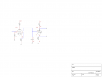
Here is my KT88 amp circuit. I can go see what I did for the values on the EF86 if you are interested. I can't remember how I hooked up the grids on the EF86 either. It's running as a triode and so are the KT88's (KT120's) I am not using any negative feedback. Using Hammond 1650N outputs. Next project is upgrading the power transformer from a Hammond 272JX to a 290HX.
Attachments
Someone suggested determining stability by building a phase bode plot. This would be by measuring, with a scope, the voltage at the feedback output relative to the input while loading the feedback with the resistance it will see.
Once I see unity gain at a 180 degree phase shift will that mean the frequency it will oscillate at?
Once I see unity gain at a 180 degree phase shift will that mean the frequency it will oscillate at?
Yes, you need to break the feedback network but then load both the network and the feedback point with equivalent impedances so that the rest of the circuit is unchanged. In practice an approsimation may be good enough.
180 deg feedback at unity or more gain means instability (roughly - ignoring conditional stability). Less than this may still mean a response peak.
180 deg feedback at unity or more gain means instability (roughly - ignoring conditional stability). Less than this may still mean a response peak.
OK, lets say I find a unity gain, 180 degree phase shift point at 100k.
I am a bit rusty, but to bring that back into phase would the step network you would use some equation with complex numbers to represent the angle? I cannot remember what it is. Something to move the angle -180 degrees.
I am a bit rusty, but to bring that back into phase would the step network you would use some equation with complex numbers to represent the angle? I cannot remember what it is. Something to move the angle -180 degrees.
No, you don't need to change the phase by 180 degrees. Just enough to stop the loop gain locus from curling around the (1,0) point. The normal lead-lag compensation network in an anode circuit works by reducing high frequency gain, although it increases phase shift over a band of frequencies. The capacitor across the feedback resistor can sometimes help by reducing phase shift, although it increases loop gain.
- Status
- This old topic is closed. If you want to reopen this topic, contact a moderator using the "Report Post" button.
- Home
- Amplifiers
- Tubes / Valves
- Quad KT88 driver