If they are indeed paper-in-oil then there are some questions to be answered, such as:
Why does the original Quad II diagram show them as electrolytics?
How, when an 8uF 600V paper-in-oil is so big, did Quad manage to fit 2 x 16uF 350V in a can half the volume?
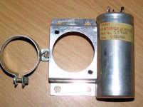
The X-ray clearly shows tubular capacitors inside the can, losing further volume.
Harking back to the earlier comment about etched foil, that's only pertinent to an electrolytic.
Why does the original Quad II diagram show them as electrolytics?
How, when an 8uF 600V paper-in-oil is so big, did Quad manage to fit 2 x 16uF 350V in a can half the volume?
The X-ray clearly shows tubular capacitors inside the can, losing further volume.
Harking back to the earlier comment about etched foil, that's only pertinent to an electrolytic.
I would also agree with the Martin Hayes....
The tar leakage is usually not a result of the power transformer failure....could be for a number of reasons.... First off we all concur the transformer is under ratted .... The filter caps, when they get old tend to increase thier DC leakage, this can add to the current load... Also the tar used has process variation batch to batch and my not always have the high melting temperarure needed... i use "Goo-Gone" to clean up all the tar..or go to auto store and by a can of tar-remover as used on automobile painted surface....
I usually take apart the transformer canister and remove as much tar as possible then seal it up with a black RTV, this will keep it from further leaking....
Chris
EC8010 said:If they are indeed paper-in-oil then there are some questions to be answered, such as:
Why does the original Quad II diagram show them as electrolytics?
How, when an 8uF 600V paper-in-oil is so big, did Quad manage to fit 2 x 16uF 350V in a can half the volume?
The X-ray clearly shows tubular capacitors inside the can, losing further volume.
Harking back to the earlier comment about etched foil, that's only pertinent to an electrolytic.
Quite right. They are electrolytics. There are three terminations on the can: two of them have a red collar, and there is a common ground, which is black. What baffles me is I remember reading some time ago that one of the praiseworthy features of these amps is that the smoothing caps are paper-in-oil rather than nasty electrolytics. As you've pointed out, on size alone they couldn't be paper-in-oil. Right now I'm holding a Dubilier 4uF 100V paper-in-oil cap and it is large (62mm x 52mm x 30mm).
Martin Hayes said:What baffles me is I remember reading some time ago that one of the praiseworthy features of these amps is that the smoothing caps are paper-in-oil rather than nasty electrolytics.
Whoever wrote that was probably confused by the fact that the can style (shape, fixing, paint colour) is exactly like a TCC paper-in-oil power capacitor.
By the way, my Quad II (which didn't supply power to anything) ran hot and regularly oozed pitch from the power transformer during the hot summers of '75 and '76.
Re: Quad Ii Restoration
You may be able to get some ideas from this thread, restoring a Leak TL12.1:
http://www.review33.com/avforum/forum_message.php?topic=82050902223555&page=1
ginsner said:
1. How do I safely clean off the tar without damaging the boards
2. What to look for when inspecting the tubes
3. What to do about the transformer that has leaked out all the tar
You may be able to get some ideas from this thread, restoring a Leak TL12.1:
http://www.review33.com/avforum/forum_message.php?topic=82050902223555&page=1
Hi Qinsner,
Having restored some 15 Quad IIs, I might venture the following:
1. The filter capacitors are electrolytics as suggested by EC8010. (Otherwise plain and etched foil make no sense.) Capacitors come much smaller these days, and I replace by a 50 + 50uF/500V JJ. It is round and could perhaps be mounted in the old can, but I did not bother. It provides for rather improved bass response (better power supply regulation). Such values would have been pretty big 5 decades ago.
2. Oozing of tar does not necessarily mean fried transformers. In fact, this is regular with the choke, with the quite hot 180 ohm KT66 cathode resistor (R12) mounted right underneath. Mount that bent away from there - I also replace by a 5W or 10W resistor.
3. For the same reason I found most C5s baked dry. Again, mount it away from R12. I also increase the value to 470uF/50V, for improved regulation. They come quite small.
4. Regarding the coupling capacitors C2 and C3. Yes, the metal cans introduced about 16pF of capacitance to earth. One can replace with 100nF/600V polyesters directly tied to the tube socket terminals. To make up for this capacitance (a square wave will have a slight overshoot without that - not serious), I mount a 1,2nF in parallel with R11. Phase lead compensation is better here, and makes for improved h.f. behaviour.
5. Also C1, replace by a 450V or higher V-type. Again, in those days these were not available in the quality that today is common.
6. Then I found that e.g. the Russian KT66s have exactly the same innards as their 6L6GC, but cost twice as much! The 6L6GC is within less than 10% of the KT66; in fact, factory spread of KT66 is often greater! The 6L6GC is usually a little smaller, which again helps keeping heat away from the power transformer, and they draw 40% less heater current. That is unless you are fortunate enough to get original KT66s, which contributes to the original appearance.
This may sound like altering the original, but that is the way it would have been built today. It is stupid not to make use of development of materials over the past 5 decades. The changes need not look at all unlike the original.
Lastly I would steer away from some of the KT66s in the "Coke-bottle" shape. They come too close to the transformers and heat them up. Eventually I found the h.t. about 360V instead of the rated 330V, resulting in an output of 19W before clipping. We have a moderately hot summer here in Pretoria, and I found no undue heat from the power transformer after several hours (but that is without accessories).
There is a number of problems with the 22 pre-amp - some capacitors drifted by over 200% - but this is getting long. Perhaps you could mention if you are going to use that, then I could comment in a further post.
And beware! Do not be tempted to use EL34s! They will ruin your amplifiers and do not work better despite old wives' tales.
Regards and success.
Qinsner,
Sorry, me again. I have just reread your original post, where you mentioned not desiring any changes except for safety reasons. Please trust that what has been mentioned are in a way for safety reasons as well as bringing things up to date. I did not mention resistors; some of those have drifted by over 40% (particularly R2 and R3) in my experience; they were probably not made for 50+years of quality.They are inexpensive; I replaced by metal film 1W types. The 1W is not always needed, but today's small resistors look silly in there!
You also asked how to judge the tubes. Hoping that none has an internal short, I would simply power up and measure. Do you have a diagram? H.t. might be about 350V, V(R12) about 26V, and the anodes of the EF86s 105 - 125V. If they differ appreciably, replace. The G2 voltages are about 80 - 90V, but difficult to measure as even a DVM changes the value. The anode voltages will show that all is in order. The EF86 cathode voltage is about 2,1V.
I also neglected to mention: The GZ32 rectifier became outdated shortly after these amplifiers were designed. It was replaced by GZ34/5AR4 - smaller, cooler, better.
And, as always, be careful when measuring! You may have tube experience, but in case not, there are uncomfortable voltages in there! Do work safely.
Regards
Martin Hayes said:According to this Quad modification website DC Daylight, ......
And says this about the CLC caps, which were originally 16uF and were paper-in-oil types, not electrolytics:
There were markings on the can that indicated each section, though having the same value, were constructed differently and had slightly different operating properties. The section closest to the rectifier was marked +P (for plain foil) and had a higher ripple rating; the section further from the rectifier was marked +E (for etched foil) and behaved more like an electrolytic.
Martin
The quote you make about C3/C4 must have been "constructed" from comments on my redrawn schematic - where I actually wrote:
"C4 is marked +E (for etched foil) and is more like a standard electrolytic"
i.e. both sections are electrolytic but the plain section is not standard.
Bear in mind that the choice of C3/C4 would have been made with size and "tropical" rating in mind considering the small size of the design compared to it's contemporaries.
Changing C3 for any good "modern" capacitors up to a total value of about 70uF (limited by GZ32) and C4 for as high as you like can lower the noise floor (mainly at LF) by more than 10dB and allows greater peak output.
Regards
Keith
DCD
Perhaps not that we didn't read, dcd,
I simply new what you were referring to without cross-checking to a component designation on a circuit diagram. And while I am responding ....
In a way the previous picture of the component board and the chassis top looked rather like it was the choke leaking pitch. I often found that mainly because of the already mentioned hot cathode resistor mounted directly under the choke. Also in general regading whether a restored Quad is an original Quad: one has only 2 options: An original Quad (in that sense) or an optimally working Quad. If one wants to only display it, one cleans off and polishes, schluss. But how would Peter Walker have built it nowadays?
I read earlier with surprise about a roll-off at the top and bottom. Not in any of those I restored. They happily work from 25 Hz - >20 KHz, or are we chasing 100 KHz just because some super XYZ appears to have that ability?
I am also restoring a couple of old Quads. They were not in their best shape, and not original. The former owner (or maybe the owner before that) had almost completely destroyed the amps. Especially one of them.
I have changed all the innards, but the cabling needs to be worked on a bit more.
http://www.hifisentralen.no/forum/index.php/topic,12798.0.html
Especially when I raised the value of c3, c6 to 47uf something good happened.
Now the amps play extremely well, and no hum/noise whatsoever. They are more quiet than my Audio Note Conquests. Soundwise the Conquests are alot better.
All the resistors are changed, so are the different caps.
Especially when I raised the value of c3, c6 to 47uf something good happened.
Now the amps play extremely well, and no hum/noise whatsoever.
The more you increase in capacitance of C4 & C6 can result in better sound quality but it'll also stress the rectifier tube and mains transformer more than its initial design. Increasing the values would of course lower any audible hum too. Nevertheless, many owners around the world have restored, hot rodded it to its limits in the signal and dc filter cap values with considerable success and gained personal satisfaction. Different kinds or a combination of types of resistors can also alter the tonal character. It entirely up to you and how much one likes to spend on generic or boutique parts.
I've come across some owners willing to pay BIG bucks on 40 year old NOS Original capacitors to obtain its original vintage sonic quality or to best maintain 100% originality. Personally I'd believe there's a huge likelihood those NOS parts from 4 decades ago could have already deteriorated along the way and can be a risk whilst in optimum circuit operation.
Bambadoo,
Greater possibility is that you replaced poor electrolytics (because of age) with good electrolytics. If one is really fanatic (er, well, enthusiastic) one can unsolder the bottom of the original C3-C6 can and mount the new caps inside. I personally use JJ 50 + 50uF/500V types and fill up the can with poly-urethane foam before re-sealing. They do stress the rectifier more, but I replace the GZ32 with a GZ34 with general advantage (slightly higher dc output, less heat from the rectifier close to the choke and output transformer). The average current of 130mA (without tuner) is low enough not to overstress a good GZ34 under these conditions.
The resistors do change quite a bit - up to +30%. I have never found the metal caps (3 x 0.1uF) wanting, but replace them anyway, 630V types then; they are cheap enough. I fear I myself am not into the "sound" of components - metal film resistors are fine as are polyester caps. I would agree with Coolmaster regarding doubtful quality of vintage caps. Not to step on toes, but "the sound of vintage caps" especially as stated by sales talk is mostly in the interest of getting rid of old stock. You can read about the metal-to-chassis capacity effect earlier as well as the cure.
IEC wiring
Resurrecting an old thread for a new question. I'm looking for a bit of 'translation' expertise.
I am fitting an IEC socket, along with general replacement of resistors, so that I can safely use my Quad II's with a 'modern' valve pre-amp.
Keith Snook's web page about modernising Quad II's refers to fitting of IEC socket with earth connected to the chassis and then "the 0V of the circuit is connected to chassis via the 10Ω resistor and parallel capacitor mounted from E of the transformer. T[SIZE=+2][/SIZE]his helps prevent earth hum loops while ensuring that the metalwork of the amplifier is safe to handle".
So, if I've got the drift of this, the IEC common terminal is connected to the COM terminal of the transformer, and the COM terminal is then connected to Earth via a 10ohm resistor with a capacitor in parallel
Anyone care to comment on my interpretation, and on a reasonable size and type of capacitor?
Sorry if these are dumb questions, but don't want to c*ck this up.
Thanks for any/all help.
J
The power supply caps are electrolytic ; I too imagined they where paper in oil but when replacing them found they are electrolytic. i have never seen a Quad that did not have tar coming out of the power trans. Read of a blind test comparing the Quad 11's to the 33/303; I don't know how they did it the 33/303 is so noisy, compared to the Tube amp. the Quad is excellent for back ground music no dynamics and poor frequency response." very pleasant listening"
Phil
Phil
Wiring guidance
Hey there Multi,
Thanks for your posting. I was actually after some wiring guidance on Snook's additions (resistor + parallel cap) to the installation of an IEC socket, i.e. have I got the routing correct?
I can no doubt use either a poly or electrolytic cap for the parallel cap, but don't have a clue as to a reasonable value. I'm guessing it's a basic RC filter.
Cheers,
J
So, if I've got the drift of this, the IEC common terminal is connected to the COM terminal of the transformer, and the COM terminal is then connected to Earth via a 10ohm resistor with a capacitor in parallel
Anyone care to comment on my interpretation, and on a reasonable size and type of capacitor?
J
Hey there Multi,
Thanks for your posting. I was actually after some wiring guidance on Snook's additions (resistor + parallel cap) to the installation of an IEC socket, i.e. have I got the routing correct?
I can no doubt use either a poly or electrolytic cap for the parallel cap, but don't have a clue as to a reasonable value. I'm guessing it's a basic RC filter.
Cheers,
J
- Status
- This old topic is closed. If you want to reopen this topic, contact a moderator using the "Report Post" button.
- Home
- Amplifiers
- Tubes / Valves
- Quad II Restoration