")
@Guillaume
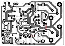
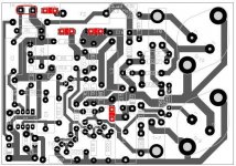
I would suggest some minor modifications to this pcb, concerning the input/output connectors and the decoupling capacitors.
1. Use of other kinds of connectors for power (+-50V, GND) and speaker out. I used 1.2mm pins but those seems thin when you have to solder heavy wires to them. I would suggest using something like this one Faston FS1536
2. Make closer the input and signal gnd, now they are 7.5mm apart but making them 5mm apart you could use some 5mm connector instead of soldering pins.
3. In parallel with C15/C16 decoupling capacitors it would be nice adding some 100uF and RC snubber across them. I'm afraid these would fit only on the solder side, but will see...
If you are not in a hurry I will do the first two mods to the pcb early next week.
You can see what I mean with the 1 and 2 in the attached image.
Attachments
Hi,
There is a whole debate on where the speaker return should go in the "Bob Cordell Interview: Power Supplies" thread, somewhere at the beginning, you should check it out.
Some clarifications on the, not so successfully, naming I've used:
GND should be rather signal ground and Earth should be power ground.
I've done the following connections:
IN - GND -> shielded cable coming from an isolated RCA. The shield at the RCA side is connected to the safety earth to minimize earth loops
+-50V -> filter capacitors
Earth -> board decoupling and other signals whose return should go to power ground. This is connected to the common star point on the PSU.
Speaker ground -> also connected to the common star point on the PSU
Out -> speaker out
I've followed Douglas Self recommendation on how to implement grounding from Audio Power Amplifier Design Handbook - pg. 402. Try to find this book somewhere or send me a pm
Regards
Just noticed that Keith Snook has added some information on his homepage http://www.dc-daylight.ltd.uk/Valve-Audio-Interest/QUAD/QUAD-405-Modification/QUAD-405-Mods.html.
A question to Zsolt!
Do you think you can help me with ordering some of your circuit boards? They look great! Maybe I can ask you for some minor modifications?
Roger
A question to Zsolt!
Do you think you can help me with ordering some of your circuit boards? They look great! Maybe I can ask you for some minor modifications?
Roger
Yes, you are right! Should read,http://www.dc-daylight.ltd.uk/Valve-Audio-Interest/Schematics/QUAD-405-Evolution-May-2008.pdf and some more here, http://www.dc-daylight.ltd.uk/Valve-Audio-Interest/QUAD/QUAD-405-2-Modification/QUAD-405-2-Mods.html
@RogerGustavsson
Yes, I noticed that Keith Snook have added some other modifications like the current source for Tr8 and complementary outputs, however, If you like these heavy modifications and want to try out something new I would suggest looking at the modifications suggested by tvicol in the thread: QUASAR a QUAD405 reborn design
Regarding with the minor modifications, what would you like me to modify? I will modify those in/out connector modifications I've said, what else?
Unfortunately I don't have as much time as I had when I've did these pcbs last year. I could send you the project files if you want to do it by yourself.
With the ordering, as I said earlier in this thread, for 2 pcbs it cost me ~45 euros. If I would like to send it to you it will cost you even more, so try to find some pcb manufacturer in your country and I can help you with the files needed by them.
Regards,
Zsolt
PCB GROUP BUY!
I would like to order PCB from factory. Does anyone feel interest too? My offer is US$24.99 for 4 pieces of PCB (1.5mm thickness, green color and have silk screen printing). Shipping (registered airmail) is included.
My e-mail: wkleung8@163.com
I would like to order PCB from factory. Does anyone feel interest too? My offer is US$24.99 for 4 pieces of PCB (1.5mm thickness, green color and have silk screen printing). Shipping (registered airmail) is included.
My e-mail: wkleung8@163.com
Kan!
I am interested in new PCBs based on Keith Snook's modification. Have been talking to Zsolt about it.
I have made some revisions to Zsolt's layout in order to make it a bit more universal.
Kan, can you give us more information on your PCBs? Are they just copies of the original Quad PCBs? Keith Snook's version have less components, giving more space for those that really are needed.
Roger
Nice Zsolt!
I have reworked my PCB. It now incorpates some more of Bernd Ludwig's original modification. I have placed a couple of transistors in the supply lines to the IC. That should remove some noises during power off. According to Bernd, only the one in the minus supply (Tr11) should do the trick but I have followed his first modification. I have also removed Tr3 and R18 as proposed by Keith Snook.
Keith Snook wrote: "The increased open loop gain using - 2SA1085E - 2SC2547E - ZTX753 - or any simular "modern" devices is more than enough and with Tr3 fitted you may find you have an RF oscillation which will not show on a scope but the distortion will be slightly higher and Tr7 - Tr8 will run hot - also it can cause blocking of the dumper drive which appears as clicks or sometimes a burst of oscillation on the negative cycles which can be seen on a scope."
I have retained the original DC-clamp circuitry. I know that Dada Electronics will have its new protection board available soon but I find it too expensive (45 Euros/channel). Those who wish can just leave the DC-clamp components out. My layout are using small Picofuse soldered directly to the board. That leaves space for some larger value capacitors in parallel to C15/C16. R30/R31 are placed on the back of the board, C10 stays cool that way. This is my latest drawing:
http://twin-x.com/groupdiy/albums/userpics/Quad405_080621_2020.GIF
Why not a group buy of components too! Some of them are not to find everywhere.
Roger
It's a good idea to have some supply line transistors to the IC, I will add them.
Indeed, leaving Tr3 in it's place increases the risk of oscillations, however, if everything is done right I think it will not oscillate. Just see that Quad has added back Tr3 in later versions as Quad 606 or Quad 909. I think they wouldn't did that if it's a problem.
Anyway, if somebody has oscillation problems, than he can take it out and use a strap instead.
Tiberiu Vicol (tvicol) raised my attention to the fact that by removing Tr3 and using the current source he suggested at Tr1 (Tr1a, Tr1b) will not be ok because:
Vce Tr1b= Vbe Tr7 + Vbe Tr3 - V R15
but
V R15 = Vbe Tr1a = 0.6V
results
Vce Tr1b = 0.6 + 0.6 - 0.6 = 0.6V which is too less.
So, Tibi's suggestion would be a diode before Tr7's emitter and maybe a capacitor over this diode. This way Vce Tr1b would be ~1.2V
So, if neither of you wants to use Tr3 than I will take it out and add a diode at Tr7's emitter. I will not add the DC clamp to the board, as anybody can buy a Velleman K4700 for ~20euro which I think is far better then Quad's dc clamp.
Zsolt
There is another solution to the original DC-clamp that Keith Snook mention.
"If you make a dual PSU as in the 306-909 you do not require d.c. protection because the output is then a.c. coupled - a point many peoble miss - I would not use use the 306-909 active ground reference for 405 but simply place a resistor from 0V centre of the supply caps to the transformer centre tap to limit the current during a fault."
Just a pity I already bought some new power supply electrolytics....(22000µF, dia 50, height 80 mm) I will not have the space for a dual set of that size. The Velleman protection is bulky and I do not know where to fit it inside the original enclosure. I do not like the way it is mounted here:
If the supply capacitors are of original size it will not fit. I have not heard about the switch-on problem that Stefaan talks about o hid homepage (I have used my two Quad 405-2 for 25 years...). Both Dada and Net Audio seems to use bipolar electrolytics in places where it is not needed. I trust Ludwig, Snook, Tiberiu Vicol and Zsolt Vadaszi a lot more!
Roger
"If you make a dual PSU as in the 306-909 you do not require d.c. protection because the output is then a.c. coupled - a point many peoble miss - I would not use use the 306-909 active ground reference for 405 but simply place a resistor from 0V centre of the supply caps to the transformer centre tap to limit the current during a fault."
Just a pity I already bought some new power supply electrolytics....(22000µF, dia 50, height 80 mm) I will not have the space for a dual set of that size. The Velleman protection is bulky and I do not know where to fit it inside the original enclosure. I do not like the way it is mounted here:
An externally hosted image should be here but it was not working when we last tested it.
. 
If the supply capacitors are of original size it will not fit. I have not heard about the switch-on problem that Stefaan talks about o hid homepage (I have used my two Quad 405-2 for 25 years...). Both Dada and Net Audio seems to use bipolar electrolytics in places where it is not needed. I trust Ludwig, Snook, Tiberiu Vicol and Zsolt Vadaszi a lot more!
Roger
I have fitted my Velleman kit behind the (original) transformer. I will take a pic if anyone's interested, as I have the casing off awaiting another mod.
I also did not use bi-polars everywhere. Seemed pointless to me. However I have used a bi-polar Black Gate for c2, and I remember it being a bit better than the Oscon used in a friends 405.
Regards, Lee.
I also did not use bi-polars everywhere. Seemed pointless to me. However I have used a bi-polar Black Gate for c2, and I remember it being a bit better than the Oscon used in a friends 405.
Regards, Lee.
vzs said:...
Indeed, leaving Tr3 in it's place increases the risk of oscillations, however, if everything is done right I think it will not oscillate. Just see that Quad has added back Tr3 in later versions as Quad 606 or Quad 909. I think they wouldn't did that if it's a problem.
...
Zsolt,
QUAD have added back the triplet in 606, 707, 909 etc, but in the same time the gain of class A stage was increased considerably.
In the original 405 the gain of class A stage is only 500/180= 2.77. Class A triplet gain is huge and this is the main reason for oscillations, but not the single one.
In 909 the whole gain of the amplifier is dictated by class A stage and was set to 500/7.5=66,(6).
Because in DCD versions, Keith Snook have decreased the gain of the OP amp stage, you can increase the gain of class A stage to 500/100=5. This will ensure a better stability and will set total gain of the amplifier to ~ 31dB.
My advice is to use a dublet and to increase the gain to 5.
Regards,
Tibi
@tvicol
Correct me if I'm wrong, but isn't the voltage gain of the class A stage=3.77 ( 180/(500+180) )?
I could change R16 from 180 to 130 and the gain of class A stage will rise to 5.
Why increasing the gain of a class A stage improves the stability of the amplifier? (maybe it's a beginner question but I'm a beginner in analog electronics theory)
By increasing the class A gain to 5 the gain of the whole amplifier will rise. Should I reduce the gain of the opamp stage to maintain the input sensitivity to ~1.5V for full output?
Thanks,
Zsolt
vzs said:@tvicol
Correct me if I'm wrong, but isn't the voltage gain of the class A stage=3.77 ( 180/(500+180) )?
...
Yes you are right. In fact (500+180)/180=3.77
Increasing the gain the amplifier will sound also less compressed.
You don't need to reduce the gain of the opamp. This was already done by Keith.
Regards,
Tibi
- Status
- This old topic is closed. If you want to reopen this topic, contact a moderator using the "Report Post" button.
- Home
- Amplifiers
- Solid State
- Quad 405 DCD mod3 - PCB