Sigma 22 is too complex in order to make profound modifications. I soldered today another 2 Q17 motherboard, the 4th one I'll finish tomorrow then I'll test each of them. Just to be sure that 4 modules are ok and work good at 59V. Then I'll return to Sigma 22 and add the TL431 and see if there is any improvement in precision (step 2). It is important to know this before going into further modifications. Maybe I might decrease the 10V difference from input-output ... that could be also important (step 3). Step 4 would be 5 amps test on both rails simoultaneously as well as independently. If the drop out would be less then 1V, then Sigma 22 is worth having in a miniaturised version. I'll keep you updated, Stef !
Ok but please open a dedicated thread in the power supply section of the forum if the design pass the "proof of concept" tests. ")
It should also be tested at 400/500mA continuous and if you are brave with 2 ZHB6792TA instead of the BCs.
Stef.
ps : do you have a kicad diagram of the v3 ?
It should also be tested at 400/500mA continuous and if you are brave with 2 ZHB6792TA instead of the BCs.
Stef.
ps : do you have a kicad diagram of the v3 ?
Hi Stef
I have some wonderful and very hopeful news for you. I have tested the circuit TL431B.
I have also made a video and extract some photos.
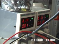
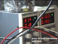
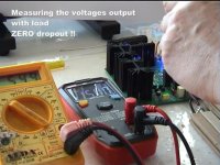
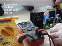
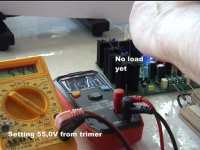
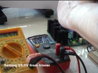
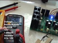
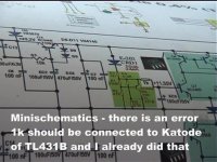
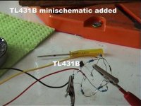
This time is zero volts dropout on 61V input and 55V output. And this time I reduced the difference input output voltage from 10 to 6Volts !!
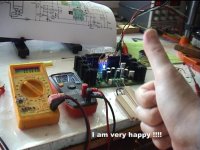
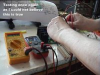
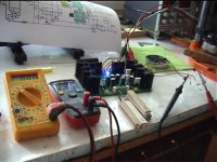
Proof attached with english text inserted on each frame.
Next, I'll try to visualise the microvolts ripple according to TL431B producers, and then go to a university lab in order to test from 1 to 5A continuous load, using a powerful variable reostat (a very big 1 meter long potentiometer).
But I am already very happy about this morning result. The photos are in order from left to right, and top to down.
Moor
I have some wonderful and very hopeful news for you. I have tested the circuit TL431B.
I have also made a video and extract some photos.
This time is zero volts dropout on 61V input and 55V output. And this time I reduced the difference input output voltage from 10 to 6Volts !!
Proof attached with english text inserted on each frame.
Next, I'll try to visualise the microvolts ripple according to TL431B producers, and then go to a university lab in order to test from 1 to 5A continuous load, using a powerful variable reostat (a very big 1 meter long potentiometer).
But I am already very happy about this morning result. The photos are in order from left to right, and top to down.
Moor
Attachments
-
 vlcsnap-2024-04-10-11h13m54s640.jpg85.8 KB · Views: 66
 -
 vlcsnap-2024-04-10-11h16m03s703.jpg72.3 KB · Views: 61
 -
 vlcsnap-2024-04-10-11h15m50s234.jpg86.8 KB · Views: 61
 -
 vlcsnap-2024-04-10-11h15m44s625.jpg70 KB · Views: 57
 -
 vlcsnap-2024-04-10-11h15m36s125.jpg82.9 KB · Views: 50
 -
 vlcsnap-2024-04-10-11h15m25s453.jpg93.9 KB · Views: 49
 -
 vlcsnap-2024-04-10-11h15m08s921.jpg90.2 KB · Views: 49
 -
 vlcsnap-2024-04-10-11h15m01s640.jpg87.7 KB · Views: 50
 -
 vlcsnap-2024-04-10-11h14m44s937.jpg86.4 KB · Views: 53
 -
 vlcsnap-2024-04-10-11h14m34s218.jpg97.2 KB · Views: 61
 -
 vlcsnap-2024-04-10-11h14m17s609.jpg89.3 KB · Views: 65
 -
 vlcsnap-2024-04-10-11h14m10s187.jpg83.6 KB · Views: 63
I have a portable minivideocamera with IR light rase and show on the screen ... I'll borrow the reostat from a laboratory for few days and then I'll return it back. Just to see how it works and variable amps ... and how much voltage drop I might encounter ... or not encounter, hopefully ...

You can use a frequency generator with a defined puls (4R load and 2/3 power ...for example) and your amp. check if its not clipping. then you can check the Voltages on the rails.
i did this at my class D TPA3255 amps to check what a SMPS is doing when caps are after. if the regulation circuit in the SMPS is slow then you might have a voltage over swing about 7 Volts!!! this can kill caps if you are on the boarder of the voltage of this caps.
i did this at my class D TPA3255 amps to check what a SMPS is doing when caps are after. if the regulation circuit in the SMPS is slow then you might have a voltage over swing about 7 Volts!!! this can kill caps if you are on the boarder of the voltage of this caps.
I already forseen the problem with caps running on the border of their voltages and even if it was much more expensive to get at 80V I prefered that instead of 65V which is quite at the maximum limit. So, that's why I was afraid of using caps at their maximum ratings which may shorten their lifetime, if not explode at certain moment. More money spent ... so what ?... it is much better to sleep with music hours every night and don't be afraid that maybe the caps will explode ... It happened with some ceramic 100nF/500V (used as snubbers) on the parallel with the rectifier, which per total voltage there should not be more then 100V and still they exploded (chinese cheap bad capacitors). But others works fine and in the past 5 years never exploded ... That is why at least on my own future Sigma 22 board I'll use only 80V capacitors, no matter how expensive they are.
Electrolytic caps are rated with a working voltage, not an absolute maximum, a 65V cap will work at 65V all day every day, but 70V might be problematic. Applying voltage to an electrolytic actually helps maintain the dielectric (hence the need to re-form old high voltage elect. caps that have been in storage).
I am afraid to use them at the voltage written on the label ... I just not feel comfortable when listening music while sleeping and maybe something might happen, and I may not hear exactly what is happening ... it is this reason too ... another reason is that before the stabiliser, the voltage from the rectifier is not constant, because of the 220V network here and sometimes is 210, 230, and because of this, I must take into the account that if I calculate from 220Vac to 40 Vac and if the 220V is rising toward 230V, then obviously the secondary voltage rise up toward 41 Volts and that 1V additional the 65Vcc after rectifier, means 67Vcc ... so I may overpower the capacitors with 2 volts beyond 65V ...
Hi everybody,
We worked a lot with Moor. We will finally be able to chat on a thread dedicated to this psu.
https://www.diyaudio.com/community/...ow-noise-linear-power-supply-50-60vcc.411727/
Stef.
We worked a lot with Moor. We will finally be able to chat on a thread dedicated to this psu.
https://www.diyaudio.com/community/...ow-noise-linear-power-supply-50-60vcc.411727/
Stef.
Hi everybody,
Here is a video test with music (link for download 7 days: https://we.tl/t-jw0vtyPhea
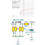
I tested a stereo Q17 modules with a newly improved constant Z quadruple potentiometer for stereo signal.
I searched an online formula graphic calculator, I have input the formula for the schematic (100k resistor and 100k double potentiometer) and the graph show at the intersection with the vertical axes, that the Z is ALMOST constant ... actually very small variations from volume zero to volume maximum.
Here is a video test with music (link for download 7 days: https://we.tl/t-jw0vtyPhea
I tested a stereo Q17 modules with a newly improved constant Z quadruple potentiometer for stereo signal.
I searched an online formula graphic calculator, I have input the formula for the schematic (100k resistor and 100k double potentiometer) and the graph show at the intersection with the vertical axes, that the Z is ALMOST constant ... actually very small variations from volume zero to volume maximum.
Attachments
Last edited:
- Home
- Amplifiers
- Solid State
- Q17 - an audiophile approach to perfect sound