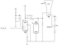
DC restorers and clamp circuits were fairly common in old black and white TV sets from the 1950's and maybe before. The video amp was AC coupled and the background brightness would vary according to the average program material unless the "black level" was clamped, or the DC level was restored. I needed a similar circuit for a "video black box" I designed about 30 years ago. See images
Tek might have done this too, it's been too many years since I fixed tube scopes.
There was an article in Audio Express or Glass Audio a few years back featuring a "new low distortion bias method." There were diodes connected to the output tubes grids. The diodes are only supposed to conduct when the output tube is already cutoff, but the driver must be prepared to drive a low impedance during this time.
I prefer direct coupled mosfet followers, they totally eliminate the problem.
Attachments
He appears to be saying that he is replacing the grid cutoff on each side by a signal clamping. The rest is just woffle. I can't see the point. If the valve still goes into cutoff then his circuit does nothing. If the valve does not go into cutoff then his circuit is increasing total dissipation, because the valve still carries some current as its anode voltage is increased by the push-pull action (thus loading the other valve too).jazbo8 said:Bob's own explanation:
"woffle...."
The circuit looks superficially like a DC restorer circuit, but that is not really what it is being used for. The high resistance in series with the diodes, and the small difference in bias voltage for them, prevents them from clamping anything. It is instead acting as a sliding bias scheme to keep the finals in class A mode longer as the signal gets larger.
When the signal peaks exceed 5 V, it starts mildly charging the coupling caps to shift the grids more positive. This hots up the tubes to stay in class A longer. The eventual grid1 conduction (with a big enough signal envelope) stops the process in time to prevent the finals from releasing smoke.
When the signal envelope returns to small signal, the bias slides back down to normal through the normal bias resistors, to lower tube dissipation again. Result is near class AB efficiency, but with low class A crossover distortion. Some inevitable small distortion on the leading edge of ramping signal envelopes though. Fortunately for them, THD testers don't dynamically ramp up the signal. Simple (envelope following, time constant type) sliding bias schemes have not fared well in the SS world. People can "hear" them adjusting. Setting the time constant long enough (high series R for the diodes) might minimize the effect, but with poorer class A tracking (too slow to ramp up or down with signal envelope).
Last edited:
Thanks for the explanation. Does this mean it will measure good but sound bad?smoking-amp said:Some inevitable small distortion on the leading edge of ramping signal envelopes though. Fortunately for them, THD testers don't dynamically ramp up the signal.
The TV video DC restore function works because the unipolar video signal contains a periodic sync pulse at the beginning of each line.
The restore diode conducts during the sync period which has a fixed amplitude, clamping the DC bias on the output side of the cap to a fixed level at the beginning of each line and preventing brightness variations that would result because of the random, unipolar nature of the video signal itself.
Every television with AC coupling in the video-signal path has some kind of DC restore circuit. Solid state TVs are much more sophisticated, using gating circuits and such, but in the end they do the same thing - keep the 0V Black level at or very near 0V.
Passive correction of DC baseline wander in an AC coupled bipolar audio signal seems problematic because of the time-constant issues. Both the audio frequency of the transient and the duration of the transient, both random, will affect performance.
Active correction is probably way past the scope of a simple tube amplifier, and has its own set of problems...
- Status
- This old topic is closed. If you want to reopen this topic, contact a moderator using the "Report Post" button.