
Hi Sy,
Is this what you mean? How does this bias the input? I know you don't like the driver config and probably the driver tube but what else is so bad about the circuit assuming I get the driver to work?
If I change to an ef86 or 6sn7 with a paraphase or diff amp input, would that be a great improvement? What is so bad about a concertina?
Thanks, Rick
Attachments
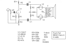
The grid resistor R4 should go from the grid to the R1-R2 junction.
The pot bottom should be grounded.
The input ground should be grounded.
A capacitor should be connected between pot wiper and grid.
Another way is to ground the R1-R2 junction and connect pot bottom + input ground there and let the power supply float. The capacitor is not needed in this case. Not recommended though.
The "problem" with the concertina splitter is that it has no gain. The input need to be the same as what the output tubes want for full power which is several volts RMS.
Look at my design earlier in this thread for a suggestion if you have a single 12AX7.
I think we are back to my original design except for the addition of the grid resistor and change of Rk.
I made the changes to schematic. Is this what you said?
I will study your design Jax, thanks. I have several 12ax7s but I don't understand the fact that a concertina has no gain. Where am I wrong on the following?
20v pk -pk needed for output each tube using a -10v bias
5.6v pk-pk max input from CDP (which is too much) using a -1v bias
A 2v pk-pk swing on the 12ax7 grid produces a 120v pk-pk swing on its plate which is split to each output grid (about a 47v pk-pk swing to each output grid)
If this is about right, then doesn't the driver stage have a gain of around 60?
Attachments
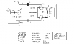
The main problem with using a split load inverter is that it requires a LOT of voltage drive. And it has pretty limited swing (headroom), though that may or may not be an issue with your app. I'd still use a simple diff amp (long-tail) to get some gain, reasonable balance, low part count, and lots of headroom.
The thing with the concertina is the large resistor from the cathode, here equal to the plate load. That resistor applies negative feedback reducing the gain. If both resistors are equal, gain will be close to 1.
This is also the reason why you add a capacitor in parallel with the cathode resistor in a normal gain stage, to restore full AC gain.
You will need 20Vpp on the input on the concertina in your circuit. (or approx 10Vpp if the output tubes should stay in class A)
Yes, the drawing is correct now.
This is also the reason why you add a capacitor in parallel with the cathode resistor in a normal gain stage, to restore full AC gain.
You will need 20Vpp on the input on the concertina in your circuit. (or approx 10Vpp if the output tubes should stay in class A)
Yes, the drawing is correct now.
Split Load
6EM7 works rather well as input / phase splitter (high mu / low mu) , otherwise I would recommend 12AY7 or 6SN7 / 5687 combination . Available HT may be your enemy here for split load , you may have to use a 6DJ8 as input stage which can work at low volatges . Partnered with a 5687 as phase splitter it's not bad but to me 12AY7 or 6SN7 makes the preferred input stage depending on required gain . CCS loading and battery biasing is icing on the cake")
316a
SY said:The main problem with using a split load inverter is that it requires a LOT of voltage drive. And it has pretty limited swing (headroom), though that may or may not be an issue with your app. I'd still use a simple diff amp (long-tail) to get some gain, reasonable balance, low part count, and lots of headroom.
6EM7 works rather well as input / phase splitter (high mu / low mu) , otherwise I would recommend 12AY7 or 6SN7 / 5687 combination . Available HT may be your enemy here for split load , you may have to use a 6DJ8 as input stage which can work at low volatges . Partnered with a 5687 as phase splitter it's not bad but to me 12AY7 or 6SN7 makes the preferred input stage depending on required gain . CCS loading and battery biasing is icing on the cake
316a
I'm not sure of what you are saying. You would use a 6sn7 or 12ay7 as input tube with 5687 as phase splitter?
You would use th 5687 in split load configuration? And, the 6dj8 would be used as input because of low voltage requirement? HT is the enemy in split load?
Oh my, I have a lot to learn!!
So, trash the 12ax7 and substitute a 5687 split load inverter. Add a 6dj8 input for gain?
Thanks,
Rick
You would use th 5687 in split load configuration? And, the 6dj8 would be used as input because of low voltage requirement? HT is the enemy in split load?
Oh my, I have a lot to learn!!
So, trash the 12ax7 and substitute a 5687 split load inverter. Add a 6dj8 input for gain?
Thanks,
Rick
fragman56 said:I'm not sure of what you are saying. You would use a 6sn7 or 12ay7 as input tube with 5687 as phase splitter?
You would use th 5687 in split load configuration? And, the 6dj8 would be used as input because of low voltage requirement? HT is the enemy in split load?
Oh my, I have a lot to learn!!
So, trash the 12ax7 and substitute a 5687 split load inverter. Add a 6dj8 input for gain?
Thanks,
Rick
Hello ,
With your 256V HT 12AY7 is not suitable as input stage , just not enough HT on tap . 12AX7 for split load duties is not a good choice at all . What is more ideal is high mu , low Ra , higher current to maximise available swing and keep Zout down (by using lower value load resistors) . 5687 is a good compromise , as is 6BL7 but come to think of it 1/2 6DJ8 may also be suitable in this spot in this application . In fact with HT this low 6DJ8 may be the way to go for both input and splitter . Using a CCS load is a must for 6DJ8 if you ask me , I find this type can sound harsh . From your diagram 6BQ5 biasing looks a bit hot (-6V/250V) : above dissipation . I would suggest a 10k a-a load at -9V 275V 40mA which should stay in class A . Also there is no facilty to DC balance the EL84 at idle , adding a 10r pot betwen cathodes with the wiper going to the cathode load may help to reduce distortion . Hope this helps
316a
- Status
- This old topic is closed. If you want to reopen this topic, contact a moderator using the "Report Post" button.
- Home
- Amplifiers
- Tubes / Valves
- Push pull class A bias question