Just got my first pair for an amp build and looked at the pinout, Why so many pins to G1? Oscillation is not my friend! What was this tube originally created for?
It's a UHF triode designed for grounded grid service (the only thing that'll work at frequencies north of 300MHz if you don't go for more exotic designs). It includes so many connections so that by connecting all of them to the ground plane you cam minimize the impedance of the ground return to prevent instability.
http://tubedata.milbert.com/sheets/009/5/5842.pdf
This was intended for rf use and with a grounded grid, it is desirable to return the input and output circuits to separate grid pins.
This was intended for rf use and with a grounded grid, it is desirable to return the input and output circuits to separate grid pins.
Thanks for the replies. Is it wise in that case to put a grid stopper on all grid pin connections if used for audio in grounded cathode config?
It might make for less noise pick-up on unconnected grid pins.
Thanks for the replies. Is it wise in that case to put a grid stopper on all grid pin connections if used for audio in grounded cathode config?
It's essential, not "merely" wise, that a Carbon composition stopper be placed on each grid connection. Arrange 4X 10 KOhm CC stoppers into a "cone". Apply the driving signal to the construct's apex.
The 5842 and the similar Russian 6С45П (6s45p) come annoyingly close to oscillating in the cardboard box. Stoppers on ALL grid connections are the 1st, but not the only, precaution necessary. Put ferrite beads on the heater power wires as close to the socket as can be obtained. Put a 100 Ω Carbon film stopper on the plate connection. While CC makes the "best" stopper, there is the issue of noise.
Not trying to be contradictory but I have been using the 5842 in designs for over 10yrs now and have found there to be absolutely no difference in the tendency to oscillate whether all 4 grid pins are used or not. Good overall layout is the most critical thing. Given this finding I use a single grid pin with a grid stopper resistor mounted right at the pin and leave the other 3 pins open. I have never had a problem with oscillation with this type, the D3A or 7788 (or any other high transconductance type for that matter) and have not been able to measure any difference in performance at audio frequencies for any possible combination of grid pins provided that oscillations are not present. (I have >100MHz scope and access to even faster ones.)
Keep components in the cathode circuit short, place the grid stopper resistor right at the grid pin used, and in cases where the output signal (Plate) is going to the outside world I place a 100 ohm resistor in series with the signal lead right at the plate. Careful planning to minimize required circuit lead lengths is a good idea.
Many people also employ common mode chokes on the filament mounted right at the socket, not a bad idea, but I have not found this to be necessary either and generally don't bother.
Metal chassis and proper grounding design help a lot. Note that I live less than 1 mile from a 10kW AM radio transmitter and have no rfi issues in my system. Wish I could say the same thing for the B*se home theater system that shares the same space..
Last edited:
I don't know this tube, but I should think the central thing here is that using it in an audio circuit is a lot different from using it in RF circuits.
Look at the data sheet. The type will oscillate if you look at it cross eyed, given its VERY high gm of 25 mA./V.
Look at the data sheet. The type will oscillate if you look at it cross eyed, given its VERY high gm of 25 mA./V.
Eli is correct, special precautions beyond what is typical for most audio types are required.
It's essential, not "merely" wise, that a Carbon composition stopper be placed on each grid connection. Arrange 4X 10 KOhm CC stoppers into a "cone". Apply the driving signal to the construct's apex.
The 5842 and the similar Russian 6С45П (6s45p) come annoyingly close to oscillating in the cardboard box. Stoppers on ALL grid connections are the 1st, but not the only, precaution necessary. Put ferrite beads on the heater power wires as close to the socket as can be obtained. Put a 100 Ω Carbon film stopper on the plate connection. While CC makes the "best" stopper, there is the issue of noise.
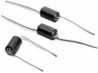
At the risk of resurrecting an old thread, what value of ferrite bead would be appropriate and would a suppressor mounted on the pin work as well?
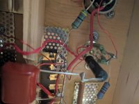
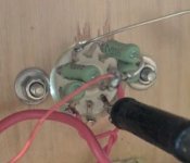
Not an answer really..but beads such as in the picture should be fine. Anything should be better than none. Also included is a picture of my 5842...without heater beads but with a cc resistor 680R on each grid (I could have cut the socket pins shorter...but I wanted to keep the socket pins intact) If I had used shitty sockets...I would have...(but these Russian military sockets are the bees knees and getting scarcer on ebay). My amp sounds lovely.
I don't think oscillation is audible? I don't hear anything amiss.
IF I ever find those little beads as in the picture in my hobby room (I know I have some)...I might retroactively fit them to my 5842.
I don't think oscillation is audible? I don't hear anything amiss.
IF I ever find those little beads as in the picture in my hobby room (I know I have some)...I might retroactively fit them to my 5842.
Attachments
Last edited:
I have always been puzzled by the advice to put a stopper on every grid pin. Yes, put a stopper on every grid pin which you connect but for an audio circuit why connect more than one grid pin? The stopper's job is to isolate the grid from the external circuit and so damp any RF resonances. Not making a connection to a grid pin also isolates that point from the external circuit. It seems to me that using all grid pins makes oscillation more likely, as the impedance between the grid and the external circuit is reduced by putting all these stoppers in parallel.
I also see no need for specifying CC resistors for use as stoppers. Why specify a non-inductive resistor when it is also suggested to use a lossy inductor (i.e. ferrite bead) as an alternative stopper? An inductive resistor and a resistive inductor can both function as stoppers. A little inductance may help, by reducing the resonant frequency of the circuit and so reducing the effect of stray capacitance and transit time effects.
I also see no need for specifying CC resistors for use as stoppers. Why specify a non-inductive resistor when it is also suggested to use a lossy inductor (i.e. ferrite bead) as an alternative stopper? An inductive resistor and a resistive inductor can both function as stoppers. A little inductance may help, by reducing the resonant frequency of the circuit and so reducing the effect of stray capacitance and transit time effects.
I don't understand it either. But do it anyway.I have always been puzzled by the advice to put a stopper on every grid pin
Again. I don't understand either why. But Morgan Jones at one stage in his book says: "The grid-stopper should be non-inductive (carbon film is ideal)"I also see no need for specifying CC resistors for use as stoppers. Why specify a non-inductive resistor when it is also suggested to use a lossy inductor (i.e. ferrite bead) as an alternative stopper?
Carbon film resistors are not non-inductive. They are spiral trimmed by LASER, which (of course) introduces inductance.
Carbon composition resistors are both non-metallic and non-inductive, which makes them very well suited to the control grid stopper role. Current in control grid circuits is vanishingly small. As carbon comp. noise is current related, noise is not an issue.
One of the reasons for using a stopper is the suppression of antenna activity. Multiple grid pins = more than 1 place for antenna activity to occur.
But since the antenna activity will take place from the pin to the end of the socket pin...or at least up until where the grid stopper is....this won't changed by adding resistors right?Multiple grid pins = more than 1 place for antenna activity to occur.
Some months ago, we've had a similar discussion on multiple grid pin triodes in this thread: Merlin RIAA Preamp . While in grounded grid UHF applications connecting all available grid pins is essential, most probably in an AF circuitry it won't do any harm to connect only one of them. Above there are given some comprehensible reasons for this statement.
Best regards!
Best regards!
I'm using carbon films. Primarily because I did not have carbon comps lying about. Since I'm very happy with the sound of my amp....this is all a bit academic...
Same here; didn't have carbon comp on hand, used film, no issues. I did have some hash in the sound using only one stopper on the grid pin I was using, so I added one to each grid pin, tying them together in a cone shape.
I call it the "cone of silence". Now all I need is a phone in my shoe.
- Status
- This old topic is closed. If you want to reopen this topic, contact a moderator using the "Report Post" button.
- Home
- Amplifiers
- Tubes / Valves
- Purpose of 5842 tube?!?