Try it now - if you have any problems, throw me an email at viktor@canopysound.dk, so we don't cluster up this threat 🙂
Hi gmarsh,
I was wondering if you've gotten further on the RN-52 module, specially on the licensing part? Did you ever get your hands on a licenced module? Or on the firmware at least?
I'm working on a small project with this module myself, before I started I assumed (...) that it supported AAC and AptX by default. Would be nice to support these codecs though.
Ordered one for delivery to USA over the weekend. Finally! Psyched. This should really help the project along.
AptX firmware isn't available, modules have to be ordered directly from Microchip with the firmware installed.Hi gmarsh,
I was wondering if you've gotten further on the RN-52 module, specially on the licensing part? Did you ever get your hands on a licenced module? Or on the firmware at least?
I'm working on a small project with this module myself, before I started I assumed (...) that it supported AAC and AptX by default. Would be nice to support these codecs though.
We got a free license from AptX themselves to buy the module, only catch is we have to slap AptX branding on our product, but we can do that. Haven't got around to ordering modules yet from Microchip - I've still got the completed bluetooth card sitting on my desk with a stock RN52 on it, where it's sat for at least a year awaiting software. Once I get that up and going, I'll look into AptX again.
AptX firmware isn't available, modules have to be ordered directly from Microchip with the firmware installed.
We got a free license from AptX themselves to buy the module, only catch is we have to slap AptX branding on our product, but we can do that. Haven't got around to ordering modules yet from Microchip - I've still got the completed bluetooth card sitting on my desk with a stock RN52 on it, where it's sat for at least a year awaiting software. Once I get that up and going, I'll look into AptX again.
Thanks for your reply! I will be contacting CSR and hope for a license 🙂
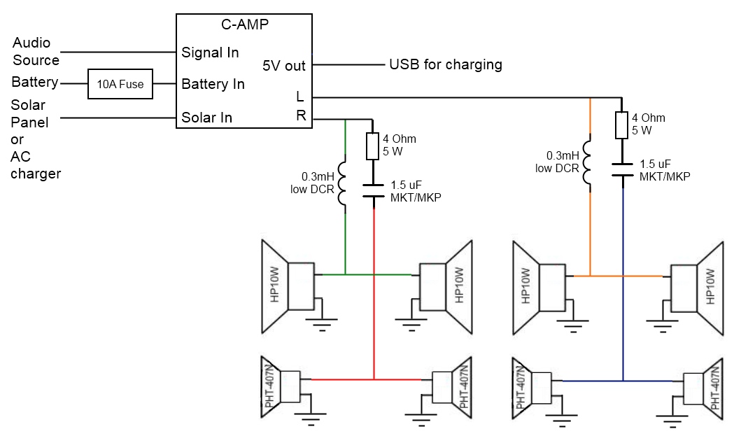
I'm going to be the biggest noob here (sorry) and ask how one would go about wiring one of these up for the Boominator (Using 4x HP-10W and 4x PHT-407N (Or if its easier, MPT-001 / KSN1001A)).
I understand enough about it to wire up the solar, battery, inputs, etc. I assume a passive crossover is needed, but this is where I have always come undone... Is a passive crossover as simple as a resister on the positive of each woofer/tweeter? Or is it more involved.
I have searched, so if I have missed something, a point in the right direction would be much appreciated!
I built a speaker box in the passed loosely based on the boominator, but I am now diving into the full setup, using every recommendation from the experts that I can!
Thanks both Saturnus and gmarsh btw, for such great work!
Edit, OK so after continued search, I found this diagram, which is perfect!
Last edited:
Ordering my cAMP soon, I do have some further questions about it though, if that's ok.
Most Solar controllers suffer from an issue, when the light is too low to charge the battery, they tend to draw a bit of power from the battery. I think you touched on this saying idle power is very low. When off (and with the amp switched off using the control terminals) is it only the LED flashing every 5s that draws power? I assume the consumption would be next to NIL if this is the case, otherwise, since I'm assuming the micro controller still needs to run, what's the general draw at night, everything off.
Also, I may have missed this part, your USB output seems to have all 4 pins accounted for, does this mean you can also play music via the USB connection from smart devices (iPhones in particular), or is this just to help aid in charging in some way?
And finally, I will have a RPi (original, 0.09a @12v), a small rougher (0.03a @12v), as well as a Bluetooth audio adaptor, by default these will all be off, but to make sure these are powered by solar first, battery second, and since the board doesn't (as far as I am aware) have a load output, would it be best to have them connected to the battery output on the card, or is it best to connect directly to the battery (since it's such a low amperage, shouldn't overload the battery).
Thanks in advance!
(Sorry for the double post)
The cAMP pulls around 1mA on average in standby mode, even accounting for the LED blinking. With a 10aH battery that's 10,000 hours or well over a year of standby time, chances are the battery's own self discharge current is worse than the amp standby current.
The USB output has a dedicated charging port control chip on it (TI TPS251x) which allows for seamless charging of both Android and Apple devices. I'm sure USB playback would be a nice feature, but it would involve putting down an XMOS or similar chipset and getting a MFI license, which would blow both the power and economic budgets.
I'm not providing a switched load output or anything, if you're running other things off the battery it's up to you to ensure they don't run down the battery.
The +5V USB output switching regulator on the card is good for 2.5 amps, I've derated it to 1A (and configured the DCP controller to advertise 1A charge current) knowing that people are gonna mount the card with poor ventilation in a black painted Boominator and probably bitch and complain when it doesn't charge their 2.1A iPad 🙂 To power your Bluetooth adapter and probably even the RPi, you can probably just power it straight off the USB output provided the current draw is reasonable. Only catch is the +5V USB output on the cAMP runs all the time unless the battery is low, so you'll have to add a power switch to cut power to your 5V stuff.
1mA is amazing, great news. I was expecting 100x that at least, the discharge on an SLA is far higher. And I generally try and discharge and recharge my battery in my original stereo one a month.
I know there is no load output on your chip, nor should there be, my needs, or wants, are different from what it was built for, I'm fine with that, I'm just wondering if there is a way in which I can wire the battery out so that it powers my other devices first, then charges the battery last. I don't think I want to use the USB, especially since I'll be panel mounting it for charging.
I just assume though, since the battery output is MCU controlled, running anything from those ports might confuse the programming, running it from the battery directly might be the way to go, since they have very low consumption, I assume the won't affect the charging or overload the battery.
I wonder, what affect it would have if I connected the devices to the solar panel side on the amp, does your circuit have anything that would stop current being drawn from that side once the solar panels become inactive, and the chip is running off battery?
All these devices have their own regulators and switches setup I should add, I am not relying on the cAMP to control them. Just wondering the best way to power them.
Thank you for you quick response, and much appreciated.
P.s. I do actually have 2 fans ready to go in if the need comes, but most likely I won't be going over 1A, don't want to add any moving parts if I can avoid it, Efficiency is key.
doctormord: I have, I've got a little black BT dongle that looks like a USB thumbdrive that I bought from DealExtreme for a couple bucks. Works pretty well.
kirtangl:
There's no "controlled battery output" anywhere on the cAMP card. The TPA3118 chip, the +5V USB regulator, a +3.3V LDO supplying the microcontroller, etc... are fed directly off the battery voltage. When the amplifier's switched off, the TPA chip is put into shutdown mode, which greatly reduces its quiescent current. When the battery goes critically low, the +5V USB regulator is shut off as well and quiescent current is then even lower.
Connect all your +12V loads to the battery, not the solar panel side. With a solar panel present and sun shining on it, the solar panel voltage is regulated to about 17V by the MPPT controller.
Nice, could you crack open it and tell me what chipset it uses? 🙂
I there any ground-lift on the c-amp?
I there any ground-lift on the c-amp?
Had it apart already, it's got a single CSR chip inside it, can't tell you the part number off hand.
I've got a "ground loop breaker" circuit on the cAMP input, similar to section 3 of this appnote - http://www.ti.com/lit/an/sloa143/sloa143.pdf - but using 100 ohms instead of 5.
Whatever you plug into the cAMP should have the audio output ground and the USB ground "sort of equal". Viktor found a Sony cellphone during testing which biased its audio input at a volt or so above ground, suffice to say it made a pretty bad racket. Devices like that will need an inline ground loop breaker transformer, which you can buy pretty cheaply.
Alright, would be interesting what's inside this thumb drive stick, as I actually doing a BT design with fly buck power rails (for isolated analog output stage and up to 42Vin) As almost all CSR chipsets only have differential out it would like to know how they implemented the diff2se stage. 🙂
Hello, Gmarsh Viktor and the rest,
Yesterday my C-AMP arrived, i did a little test run, very excited about the product.
But i want to use solar panels for my radio, but the panels once suggested by Saturnus are not available anymore so know i'm looking for something else. Is there a special type of solar panel you can recommend?
Yesterday my C-AMP arrived, i did a little test run, very excited about the product.
But i want to use solar panels for my radio, but the panels once suggested by Saturnus are not available anymore so know i'm looking for something else. Is there a special type of solar panel you can recommend?
- Home
- Amplifiers
- Class D
- Purpose-built Boominator PCB project