Hey Spent,
Corny design! No tone shaping controls? How come you decided using 6AS7 as output tube? It would be much easier to use a triode strapped like a 6V6, to have the possibíllity to to compare triode to pentode. And why low mu drivers throughout the chain? Seems to be a design made without having any experience playing/building guitar amps. Where are the decoupling cathode capacitors? Any ideas on what to expect soundwise from your design? I see you are using LTSpice, have you actually done any sims?
Lots of questions, but I am puzzled by this odd circuit") .
.
Corny design! No tone shaping controls? How come you decided using 6AS7 as output tube? It would be much easier to use a triode strapped like a 6V6, to have the possibíllity to to compare triode to pentode. And why low mu drivers throughout the chain? Seems to be a design made without having any experience playing/building guitar amps. Where are the decoupling cathode capacitors? Any ideas on what to expect soundwise from your design? I see you are using LTSpice, have you actually done any sims?
Lots of questions, but I am puzzled by this odd circuit
.Nice catch. I'll have to investigate that. To be honest I haven't had a great deal of time to compare my actual operating points, compared to my math work, estimates, and assumptions.If there is 200v on the K passing through 3.85k, Ohm's Law says you have 52mA of idle current. Maybe it's just sim entries departing from the actual operating numbers.
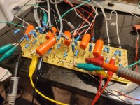
I was side tracked with noise for a while. I didn't want to send that awful hum to a dummy load and ignore it. Shielding the input helped a lot. So did sorting the rats nest of jumpers I managed to wave. Hopefully elevating the heater helps?
To the noise issue, I know you designed in the 1M input impedance to match a guitar's needs, but you also then have 1M on all the other grids. Having high input Z is asking for oversensitivity to any noise source. Did you choose those values because of weak drive to the outputs? I also see now on the data sheet that having fixed biasing isn't recommended. It may not be a good idea to have any fixed (+) grid voltage on that tube, even if 1/2 of the biasing is on the K.
Last edited:
I'm not going to argue with that. Fair assessment. I've built tone shaping controls, that is the least of my concerns, and can always be added. The additional complexity is not necessary, when I'm attempting to learn concepts that have to do with the DC operating point. I wanted to depart from any known design in order to learn more. I'm not looking for easy. Anyone can copy a 60 year old design.Hey Spent,
Corny design! No tone shaping controls? How come you decided using 6AS7 as output tube? It would be much easier to use a triode strapped like a 6V6, to have the possibíllity to to compare triode to pentode. And why low mu drivers throughout the chain? Seems to be a design made without having any experience playing/building guitar amps. Where are the decoupling cathode capacitors? Any ideas on what to expect soundwise from your design? I see you are using LTSpice, have you actually done any sims?
Lots of questions, but I am puzzled by this odd circuit
I already have built a fender champ, class A, as well as a bassman, class AB. Both with tone controls.
So why the 6AS7? I already have two 6L6 6V6 amps. I only own a small box of tubes. I'm building this entirely from items I already own. On the plus side, it's two elements in one, less soccets and real estate, less complexity. It is 13w per side so that's a plus. It is also pretty linear.
As far as the 6SN6. I don't own a lot of tubes, and I was not going to use a 12AX7 for the same reasons listed above. It shares one attribute. It's far more linear then the rest of my choices. It offers enough gain the the job. Most of all. I have 8 of um. I won't be sad if I toast it.
You mention it seems to be designed from no experience. No bleep. I started the post saying it's my first time.
I mentioned in a previous comment I overlooked the cathode capacitors. They are in fact, in circuit.
What to expect sound wise? Yeah. First it has a ton of capacitance. It's what I had on hand, and intended to go higher then fender did. A result. No sag. As you mentioned no tone. It's voiced flat. On top of that they are all biased as such it is linear with headroom. More like hifi then guitar.
I literally just downloaded LTspice yesterday. I have no idea how to use it. They make nice schematics though. I figured it was better then my chicken scratch on a scrap of paper.
Thanks for the feedback. I still find that helpful.
You have a good eye. I chose 1M everywhere because the coupling caps. The ones I have on hand are big orange drops at 1500v in order to withstand the output tube being pulled, and b+ shooting to the moon. I also idn't want the bass to roll off with the value caps on hand. Mostly, because I don't know any better. Seems that could be an area of improvement. Thanks!To the noise issue, I know you designed in the 1M input impedance to match a guitar's needs, but you also then have 1M on all the other grids. Having high input Z is asking for oversensitivity to any noise source. Did you choose those values because of weak drive to the outputs? I also see now on the data sheet that having fixed biasing isn't recommended. It may not be a good idea to have any fixed (+) grid voltage on that tube, even if 1/2 of the biasing is on the K.
I'm aware of the fixed bias issue. I'm willing to risk it. Fingers crossed that one the combination of both keeps the tube happy
Last edited:
Yup. I made a mistake somewhere along the line. The 1.4k is fine. The 2.45k should be 1.67k. I'm reaching some of the odd values by dropping most of the current across a slightly larger resistor, and adding a high value in parallel. I better check out the physical amp for this mistake and go through all the voltages.If there is 200v on the K passing through 3.85k, Ohm's Law says you have 52mA of idle current. Maybe it's just sim entries departing from the actual operating numbers. I think your loadline sim is being thrown off by having both grid and K biasing.
To be honest, I haven't come to completely understand why fender chose that value. It's currently on a switch to half that resistance, but I have yet to experiment with the ac side of things. In all my attempts to copy nothing. A few things slipped by.Why the 68K grid stopper on the input? It seems rather large. I have seen it used on quite a few guitar amps and thought maybe it was just copied from an early Fender and has just proliferate.
I couldn't find the reply to quote. But I think I see what you meant in regard to a choke input. Were you suggesting the first thing the rectifier sees is a choke, rather then a capacitor? I've seen doing Google searches this subject, and I don't think I was understanding. They suggested a small cap to reduce the max voltage swing. I did not understand what they meant, and maybe what you meant. I think I'm on to it now. The choke is up front where the voltage is swinging. Greater voltage drop across it. I've been operating under the assumption it's always best to have as much capacitance you can up front.

I don't want to a spam my own post but I need to summarize.
All that being said. Can I make it work? I still think so. I may be stubborn and push forward. I've learned more physically doing this so far then 1000 hours of YouTube have done. YouTube, and Google kept me from burning a tube so far. Actually doing it has tought me way more.
- it's intended to be a guitar amp, but it's a Corny design that is flat and lacks tone.
- the b+ is *** backwards. First the inverter, then the preamp, then the output tubes.
- it's 1m on all the grids to ground. This should only be true on the first stage.
- Investigate the 68k resistor on the input
- double check it's actually operating where I estimated
- elevate the heater
All that being said. Can I make it work? I still think so. I may be stubborn and push forward. I've learned more physically doing this so far then 1000 hours of YouTube have done. YouTube, and Google kept me from burning a tube so far. Actually doing it has tought me way more.
Most common B+ topologies have the output tranny center tap "first", then some drop and filter to the output tube driver, then some more drop and filtering to the "preamp". What's with the 50W resistor dropping B+ to the tranny center tap? Maybe that's not how it's wired anymore...the b+ is *** backwards. First the inverter, then the preamp, then the output tubes.
Most common B+ topologies have the output tranny center tap "first" in the chain, then some V drop and filter to the output tube driver, then some more drop and filtering to the "preamp". What's with the 1.4k, 50W resistor dropping B+ to the tranny center tap?the b+ is *** backwards. First the inverter, then the preamp, then the output tubes.
Maybe that's not how it's wired anymore...
Flat can describe not just EQ, but how the amp behaves dynamically under transient conditions. For guitar, those transients come from a series of someone really whacking the strings with "rests" of silence in between. The big current yank on the power supply is going to come from that B+ tranny connection. Having a hard time imagining that at the end of the B+ filter string.
Not that I know how to design a power supply B+ for the most musically useful sonic character in a guitar amp. Within certain vintage amplifiers, I would have to assume that some voltage droop with load current happened, due to design choices made from practicality (power tranny size and filter capacitance) and the resultant sound dynamic became desirable among players over the decades.
It's actually a goldilocks / 3 bears problem; too soft, too hard, just right. That's just the voltage droop amount; there's time constants too; droop slow / recover fast or droop fast / recover slow - or - is the droop and recover time equal? For most musically useful behavior.
So the power supply in a guitar amp isnt just to get hum free DC to the tubes. By way of how it reacts to current loading, it changes the operating point of the tubes and hence, how the amp sounds. The "too hard" power supply I suspect could make the amp sound "sterile" for example. Loud, yes. Dynamic, yes. Sterile as a knife edge from an autoclave.
Here's something I wonder if anyone's tried; instead of the typical CRC RC RC string for a B+, put the output tubes on their own fork, so the voltage going there can droop without effecting the preamp and driver B+ at all. Or, put a diode in the typical B+ string so when the output tube loading crushes that first capacitor, the diode blocks it from pulling charge out of the subsequent caps.
I dont claim to know what any of that would do, but just goes to show some thought and imagination could be applied to the B+ power supply design, that perhaps get you something in how your amp works when playing music through it from a guitar.
All that being said. Can I make it work? I still think so.
I think it'll be closer to being a stable build once you change the PS to choke input. The B+ will be in a more customary range. Less complicated filtering scheme with the voltage rating on the caps. Do you know the OEM rating on the PT? I'm guessing it's @500 -550v CT.
- Home
- Live Sound
- Instruments and Amps
- Pure class A guitar amp design help