What is the best way to attack these amps. Right now I have no output on either channel, but I have a clean signal leaving the input board. I pulled the output fets so I wouldn't have to worry about them shorting. I did find one transistor shorted on the driver card, believe it was a PNP (3B) BC856. Could a 2G transistor be sub'd for this?
I have two of these amps and both have the same problem. The 10uF caps have all been changed, if they needed it or not.
cory
I have two of these amps and both have the same problem. The 10uF caps have all been changed, if they needed it or not.
cory
The MMBTA56 should be a good sub.
With the outputs out of the circuit, you can't do much troubleshooting of the audio section with the amp powered up. Do you have a clean signal on pin 1 and no signal on pin 2 of the left channel and the reverse for the right channel?
Beyond that, virtually everything is in the feedback loop and depends on the feedback from the outputs to determine the voltage on the various components.
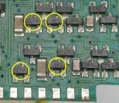
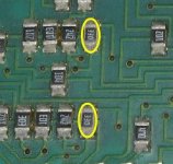
The attached images show the most common components to fail on the driver boards (assuming that you have this version of the driver boards).
With the outputs out of the circuit, you can't do much troubleshooting of the audio section with the amp powered up. Do you have a clean signal on pin 1 and no signal on pin 2 of the left channel and the reverse for the right channel?
Beyond that, virtually everything is in the feedback loop and depends on the feedback from the outputs to determine the voltage on the various components.
The attached images show the most common components to fail on the driver boards (assuming that you have this version of the driver boards).
Attachments
Paint should be outlawed. Download Open Office (free). It has a 'Draw' application that's infinitely better than Paint.
Email me before you do any more on this board.
babin_perry@yahoo.com
Email me before you do any more on this board.
babin_perry@yahoo.com
Is that the same resistor (one end connected to the emitter of Q112 and the other end connected to the negative regulated 12v)?
If so and you read 0.000v across it, there is no current flowing through constant current source and the differential pair so there's no way for the amp to produce audio. Try removing Q114 from the driver board to see if the current across that resistor increases.
If so and you read 0.000v across it, there is no current flowing through constant current source and the differential pair so there's no way for the amp to produce audio. Try removing Q114 from the driver board to see if the current across that resistor increases.
Send it to me.
babin_perry@yahoo.com
That's still not enough. I'd expect ~8-10v across the resistor that's connected between the emitter of the CCS transistor and -12v.
What is the voltage across R112 and R113 on the driver board?
Also measure the DC voltage from the supply side of the resistors to ground.
babin_perry@yahoo.com
That's still not enough. I'd expect ~8-10v across the resistor that's connected between the emitter of the CCS transistor and -12v.
What is the voltage across R112 and R113 on the driver board?
Also measure the DC voltage from the supply side of the resistors to ground.
- Status
- This old topic is closed. If you want to reopen this topic, contact a moderator using the "Report Post" button.
- Home
- General Interest
- Car Audio
- Punch 40DSM no output on either channel