copy
Including the tied together heatsinks and the dual cheapo transformers in the case, amazing.
Yours looks like a 1-on-1 copy of a version that was posted a couple of years ago.
(with a lot of problems, one of which was tapping of the heatsinks, cured with that exact same wire/screw setup)

I was only asking for clarity of the design that was copied. I think Jacco hit on it that the design that was copied had problems. Now in round 2 there are still problems.
I can't believe it was a "bad lot". There is always a reason. Have you tried moving the transformers and power supply away from the boards. (think 2 cases) I don't know if those transformers might be creating the wooshing noise as they power up, but it is possible.
I can't believe it was a "bad lot". There is always a reason. Have you tried moving the transformers and power supply away from the boards. (think 2 cases) I don't know if those transformers might be creating the wooshing noise as they power up, but it is possible.
it's not possible .
I remember those form pics , and also remember huge problems , not just with pcbs (which I offered to replace ) but also with some unusual setup - separate boxes for attenuator , attenuator after Pumpkin etc.
I'm not going into debate from whom you are given with that bad package , but I can't remember that whooshing noise was a problem
anyway - even in case that pcbs are problematic , there is slim chance that both of them are problematic in same way ;
also - semis I was sending with pcbs were matched and tested , so these can't be a culprit , but some systematic mistake you made on both pcbs .
regarding quality of Shunty as regulator .... there is no need to waste my breath ; It's on par with anything you can find , commercially or not .
even Papa Borbely's super shunt reg , filled with preputium Toshiba Jfets and expensive mosfets , is not better .
regarding grounding scheme - this thread have just 3K posts ........ and there is also another - purely technical thread ( in my sig ) which have less posts ; I posted several times various grounding schemes , each one for particular case .
Pumpkin & Shunty , even if simple in nature of amplification of signal , aren't project for faint of heart .
there are just few active parts in amplification , but many parts around , in supporting role .
Andy said you were going to send replacement PCBs but they never arrived.
Unfortunately he is now in hospital, terminally so, that is why he has given me these bits and pieces. Even with a fresh set of eyes I can see no errors in the construction. Maybe there are some errors on the PCBs which he found with the Shuntkys. There is still the issue with large amounts of PSU noise.
Stephen
Yes I agree.
I'm going to start by separating out the four modules to see if any combination work as expected.
The two 40V transformers were used because they were EI rather than a single 40-0-40 Toroid.
I'll even go as far as trying DC supplies to the Shuntkys.
Something is wrong somewhere and its not in component choice, component orientation or soldering. Andy and I are are both seasoned electronic engineers as well as DIYers.
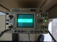
Well I finally got one of the Shuntkys out of the box and put it to the test.
The results aren't as good as I expected.
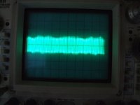
With the Shuntky miles away from any electrical equipment, including its transformer, I get a 20mV 20MHz ripple on the outputs.
Is this normal ?
The results aren't as good as I expected.
With the Shuntky miles away from any electrical equipment, including its transformer, I get a 20mV 20MHz ripple on the outputs.
Is this normal ?
Attachments
Now this is getting ODDER.
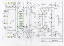
Those not familiar with the Shuntky, I have attached the Schematic.
I decided to measure the 100Hz (UK 50Hz supply) ripple at the output of the CRCRC filter, it was huge, almost 100mV Pk-Pk.
Simplest thing to do was to remove the two fuses OS1 and OS1A. With the fuses removed the CRCRC circuit is as close to silent as I can measure.
YES, the Shuntky is supposed to pull current, but not to the extent where the input supply is compromised.
Attachments
Last edited:
I don't understand the circuitry well enough to start pulling components to see what is and isn't working.
It outputs +/- 36V OK.
Andy did tell me that he had problems around the zener chain until it seemed to sort itself out. Nothing popped but there was some arcing around the diodes.
It outputs +/- 36V OK.
Andy did tell me that he had problems around the zener chain until it seemed to sort itself out. Nothing popped but there was some arcing around the diodes.
- Home
- Amplifiers
- Pass Labs
- Pumpkin preamp - ordered by Steen , official making thread