PedroPO said:Hi all.
I'm looking for a relay to switch an aleph 5 on and off, like Edwin Dorre used on his amp.
If anyone uses such a relay and know is brand/part # please advise.
thanx,
I found what I used:
A DOLD relais:
http://www.dold.com/deutsch/Leiterplattenrelais/hauptteil_fernschalter.html#OB5693-94
datasheet:
http://www.produktinfo.conrad.com/datenblaetter/500000-524999/505510-da-01-de-stromstossrelais.pdf
this one is available in 230V-AC ...
Have fun,
Edwin
Banned
Joined 2002
Well, here is another type of impulse relays, better, same type other application from telemecanique. It's a impulse relay to be used in electrical instalations like corridors or stairs. it is for rail mounting, but it functions the same way of the others.
(funny I'm answering my yesterday question?!)
(funny I'm answering my yesterday question?!)
Here is a relay from Finder that should work for this job.
it is a dual pole NO step relay 230 VAC operated 10A that is operated with a impulse button.
P/N:26028230
www.findernet.com
it is a dual pole NO step relay 230 VAC operated 10A that is operated with a impulse button.
P/N:26028230
www.findernet.com
 and costs at a local electrical shop €8.00
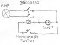
Fun with LED's
kristijan-k, do you know where I could tie in LED's into your circuit?
I was thinking one for standby and another for power indication. Would my relay need to be double pole in order to do this? I was thinking I could connect one of the poles between the standby and power led loops, while the other pole would be connected between the AC line voltage for the amp.
What do you think?
Thanks,
Wes
GE RRx relays
These things aren’t exactly what you guys have been talking about, but I thought they might be worth mentioning here. Its a solenoid operated toggle switch made in all kinds of sizes by GE. The ones I used had three connections for the coils; a common, on and off. a 24vac pulse between common and one of the states would set the toggle switch to that state.
I’ve been able to source them from my corner lighting supply house for about $15 a piece.
They also feature low current contacts to indicate off and on positions.
http://www.geindustrial.com/cwc/products?pnlid=3&id=tlc-rely&SMSESSION=NO
They are very tough and very reliable.
Attachments
Hello Wes,
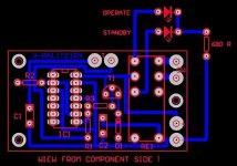
If you would like to have LED indication for the ON/OFF
of the pulse switch, you can use the method attached below.
Also, instead two separate LEDs, you can use one of
those that have 3 pins (3 color), and this way have
just one LED but with different colors for the ON and OFF.
Best regards,
Kristijan Kljucaric
http://web.vip.hr/pcb-design.vip
Attachments
I dont know that this is the best device for the application, but I thought I would toss it out for discussion. Most notably I could not find any reference to a DPST version that could be used for switching hot and neutral together. I like the aproaches taken by Kristijan-K and PendroPO.
These things seem to exist mostly for use in lighting control systems for large buildings. I first ran across a box full of them about twenty years ago, and the ones I found were old then. They seem to be a relatively jurassic technology, but elegant none the less. I have a large home wiring project coming up and have been thinking about using some to enable low voltage controls.I have some recollection of a wiring sheet included in the box with the relay. I also remember cutting off the Molex looking connector and spending a little time noodleing over it with a transformer ohm-meter.
The GE site tells me that there are five low voltage wires. I will submit that it one of those wires will be a common or neutral connection. The remaining four wires would have two for operation and two for indication.
For operation applying a 24VAC pulse between the common and operating line would set the switch to appropriate position: Set the switch on, and set the switch off.
The indicating lines would be two SPST closures (or one SPDT depending on where your standing). One line would be closed between common and itself when the switch was set to the on position, and one would be closed when switch was set to the on position.
Attachments
Thanks
Thanks kristijan,
Thats exactly what I was looking for. I've been doing some research and I found this relay...
http://www.findernet.com/en/products/detail.php?codice=405290090000&lang=en&gruppo=gruppo3
This looks like it will get the job done; however, I am using it in place of the line switch for a Leach Amp.
Prof. Leach reccomends a 15 A or greater AC line switch. Although the relay above is only rated at 8A.
Question: this is 8A at 250V according to the chart right? ... so this should be 16A at 110-120 V?. 16 A at 120 V is 1920VA, which is under 2000VA. So this should work right, or am I way off?
Also it is DPDT which is what the circuit calls for right?
Thanks for bearing with me on this one, I am a rookie.
Thanks,
Wes
Off topic or perhaps subtext:
I found this company that builds home lighting control systems that use lots of GE RR7 and RR9 relays. The house we just moved into has lots of aluminum wiring that has all got to go.
http://www.touchplate.com/index.shtml
I'm hopping that this company will have a cost effective approach to low voltage control. A lot of these guys want to charge $200 bucks for a plate with two SPST push buttons on it, and all it does is act as part of a replacement for a $2 toggle switch.
If these guys don’t work out I'll likely start building my own low voltage switch panels but yikes there will need to be a bunch of them.
I forgot to mention one of the neat things about the GE relay. The solenoid outside diameter is sized to fit in a standard electric box knock out.
One controller I built had to RR9s on one side of a 1900 box with a 24VAC transformer on the next. I screwed a barrier strip to the back of the box to make all of the low voltage connections. Neat, small, and simple, just like my wife describes me!
I will now return you to your normally scheduled program.
-Dave
- Status
- This old topic is closed. If you want to reopen this topic, contact a moderator using the "Report Post" button.
- Home
- Amplifiers
- Pass Labs
- Pulse Power Switch