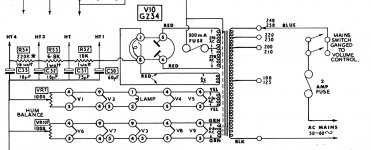
I have a transformer from an old heathkit s99, I presume it is approx 200ma but I'm not sure. I've attached a schematic for the circuit it came from. It was powering 4ecl86 and 3 ecc83's and 2 ef86's.
I have no idea of what values to enter into duncans psu designer, is the RMS V = 270 x 1.414 = 381V - and then how do I calculate the source resistance?
Is there a way to calculate more info from this transformer seeing as on the full scematic
HT 1 = 320V
HT 2 = 270V
HT 3 = 250V
cheers Stuart
I have no idea of what values to enter into duncans psu designer, is the RMS V = 270 x 1.414 = 381V - and then how do I calculate the source resistance?
Is there a way to calculate more info from this transformer seeing as on the full scematic
HT 1 = 320V
HT 2 = 270V
HT 3 = 250V
cheers Stuart
Attachments
"I have no idea of what values to enter into duncans psu designer, is the RMS V = 270 x 1.414 = 381V - and then how do I calculate the source resistance?"
look at the data sheet for V10: GZ34
http://www.wooaudio.com/docs/tube_data/5AR4.pdf
Hope that helps.
look at the data sheet for V10: GZ34
http://www.wooaudio.com/docs/tube_data/5AR4.pdf
Hope that helps.
Thanks Df96, I didn't realise I could just stick a DVM on primary winding (mains side?) and then over the secondary winding (leave CT out?) to get resistances - that I could then apply to a formula to find the source resistance!
If I then setup a circuit in PSUD2, using full wave rectifier (GZ34) followed by CRCRC will I be able to identify the current throught the circuit by seeing what flows through the final 5K resistor that PSUD2 puts in by default?
Or do I change that final 'resistor to ground' to a resistance that matchs the perceived resistance of the amp I wish to build?
If I wish to build the original Baby Huey amp that gingertubes modded for UL operation, should I be changing the value of the final 5k resistor of PSUD2?
Thanks again for everyones help here, and thanks Dug for the data sheet

That may be a reasonable estimate. You can calculate quiescent current by using Ohm's Law on the cathode resistors. A typical push-pull Class A output will increase its current draw by 10-20% at full output, but that will only be on music peaks so can almost be ignored. Class B will increase more, of course.
A design should say what current it draws. The designer must know, because it is part of the design process.
A design should say what current it draws. The designer must know, because it is part of the design process.
Great guys thanks...
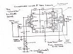
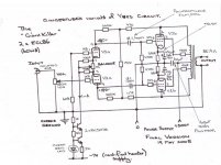
So for the circuit posted below I can assume that V across the cathode of final stage is 10.5 V and the cathode R is 390ohms...
Therefore I = 10.5 / 390 = 0.0269 or 27mA
This is the idle current which would be the same as the quiessent current seeing as this amp operates mainly in class A (is this correct?)
and.... I,m still trying to figure out how the first stage only draws around 1mA and has a constant current source to determine this...
my limited background in physics always taught me that the current was the same for the entire circuit?
Attachments
Source resistance calculated 1
Ok, thanks to all here - I'm making headway!
primary resistance = 9ohms
secondary resistance = 63ohms (CT to Sec)
Source resistance = (primary resistance / (Vpri/Vsec)2) + Secondary resistance
Vpri = 230
Vsec = 270
(Vpri/Vsec)2 = 0.726
therefore Source resistance = 75.3ohms
Ok, thanks to all here - I'm making headway!
primary resistance = 9ohms
secondary resistance = 63ohms (CT to Sec)
Source resistance = (primary resistance / (Vpri/Vsec)2) + Secondary resistance
Vpri = 230
Vsec = 270
(Vpri/Vsec)2 = 0.726
therefore Source resistance = 75.3ohms
- Status
- This old topic is closed. If you want to reopen this topic, contact a moderator using the "Report Post" button.
- Home
- Amplifiers
- Tubes / Valves
- PSU id and help (psu designer ii)