Hi, I have a question about the right PSU for this tube. I'm using a transformer with 270 VAC that should be about 170 VDC for B+. I've seen with three suitable RC filters that voltage drops to 180 V (found with 2K resistive load), but when I try to wire the tube it jumps over 300 V. Did I make some mistake? The tube glows regularly and the filament PSU is perfect.
What is your DC voltage at the bridge, and what is the total current you will need from the PSU? What is the amplifier circuit you will be feeding?
A mosfet based ripple filter (with a big heatsink!) that has the gate fed from a voltage divider would work very well to drop the voltage you need, a bit more "predictable" too. Could even set a reference voltage at the gate with a stack of zener diodes to give a very good little open loop regulator with excellent performance. Dropping that much voltage and current through those RC stages will not be as stable. A single IRF820 and a few resitors (and zeners if you like) would be a better fit.
A mosfet based ripple filter (with a big heatsink!) that has the gate fed from a voltage divider would work very well to drop the voltage you need, a bit more "predictable" too. Could even set a reference voltage at the gate with a stack of zener diodes to give a very good little open loop regulator with excellent performance. Dropping that much voltage and current through those RC stages will not be as stable. A single IRF820 and a few resitors (and zeners if you like) would be a better fit.
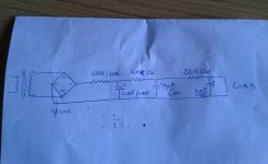
270 vac x 1.41 ... = 380 Vdc peak
470 R + 470 R + 220 R = 1160 R
You are seeing 300 V, -80 V from peak
E = IR
I = E/R = 80/1160 = 77 mA
You WANT 170 V = (380 - 210 V)
Figure your current to also drop proportionately
77 mA * (170/300) = 40 mA
R = E/I = 210 / 0.040
R = 5000 ohms all told
Break into thirds, substitute into your PS design at each position
1.6 kohm each...
Of course if current does NOT scale do calcs again to accommodate
Also, figure power dissipation
P = E2/R = (1/3 210)2/1600 = 3.1 Watt ea
Use 5 watt resistors at each position.
Just saying...
GoatGuy
PS... LingWendil's observation of MOSFET regulation is spot on. I personally prefer BJTs, but it's just "style". It frees the power supply from slumping and surging under varying load.
You can also get rid of a whole RC section.
The heat sink needs to dissipate 25+ watts tho!!!
GoatGuy
You can also get rid of a whole RC section.
The heat sink needs to dissipate 25+ watts tho!!!
GoatGuy
Just a thought,
The op says he gets 180 volts with a 2K load resistor. Using the 1/3rd to 2/3rds potential divider idea (1160 to 2K load) he should really be seeing 240/250 volts from a 380 volt off load supply?
If the transformer is from a radio, it may not have a sufficient current capacity to hold the voltage up.
As was said earlier, you are dissipating an awful lot of heat loosing 200 volts.
Indaco, do you know how much current the 6N13P is drawing in total?
DC voltage at bridge is 350-360 V, my current needing is about 90 mA.What is your DC voltage at the bridge, and what is the total current you will need from the PSU? What is the amplifier circuit you will be feeding?
The circuit has been suggested by Artsalo, with first stage 12AU7 and gain stage 6N13P (let's say the circuit is similar to that of 6SN7 + 6080 headphone amplifier).
I could put here the LTspice schema
OK,
You want 180 volts, that is about half of your supply at 360 volts. Ohms law says your 'load' is 2K ohms (180 divided by 90ma = 2000). So the resistors in the filter chain must also add up to 2K. Then you have a potential divider at the half way point.
BUT as has been said you need 25 watt resistors in the filter chain. Power is V x I so 180v x 0.09A = 16.2 watts!
I would also be concerned that an old radio transformer will only give you 40 to 50mA HT current. Do you know the current rating or what valves / tubes were in it?
It might be easier and cooler to find a transformer closer to the voltage and current you are asking for...
It might be easier and cooler to find a transformer closer to the voltage and current you are asking for...
I don't know exactly what and how many tubes fed it...I know it's a Grunding transformer, from my sommary calculation and considered its weight is 1.7 Kg it should be 50 VA or more.
At this point I'm thinking it would be better change transformer though
Just use one of these... Set it at 200V.
DC-AC Converter 12V to 110V 200V 220V 280V 150W Inverter Boost Board Transformer | eBay
Power it with a 12V SMPS. You can heat the tubes with it, too.
AC 110V-220V TO DC 5V 12V 24V 2A 10A 15A 20A 40A 60A Switch Power Supply Adapter | eBay
DC-AC Converter 12V to 110V 200V 220V 280V 150W Inverter Boost Board Transformer | eBay
Power it with a 12V SMPS. You can heat the tubes with it, too.
AC 110V-220V TO DC 5V 12V 24V 2A 10A 15A 20A 40A 60A Switch Power Supply Adapter | eBay
A full wave choke input would put you at about 240V before CRC. A lot closer to where you need to be. Here is a good reference I use every once in a while:
http://www.hammondmfg.com/pdf/5c007.pdf
If I remember correctly, when using choke input, never run it without a load or the choke may fry. For more info, look up the PSU section in the Radiotron Designer's Handbook available as pdf on the www.
http://www.hammondmfg.com/pdf/5c007.pdf
If I remember correctly, when using choke input, never run it without a load or the choke may fry. For more info, look up the PSU section in the Radiotron Designer's Handbook available as pdf on the www.
That's a lot of voltage to drop across resistors. A suitable choke for that mA load would be roughly 40H for good ripple reduction; far superior to RC stages IMHE of course. As others have pointed out a choke input would be a better way to go. Sorry for the deviation to your original plan.
- Home
- Amplifiers
- Tubes / Valves
- PSU for 6N13P tube