Do you already have the power transformer or can you still be flexible? Can you post the model or specs for it and tour target B+ voltage, that would help.
The power transformer is as follows:
370V B+ not centre-tapped, guessing about 700mA (waiting to hear back from manufacturer regarding real current rating)
2x 6.3V 3.5A (for left and right output tube heaters)
1x 6.3V 3A (for preamp & phase inverter heaters)
2x 5V 3A (for rectifier heaters)
Target B+ is between 400~440V. It will run 2x 6550 tubes in push-pull triode configuration.
I've used 60V wire for 500V without issue because the current is low.
Just to amplify from another post above, the fact that the current is "quite low" has almost nothing to do with the amount of insulation needed to make the wiring safe against high voltage. The only case where the current has a bearing on things is the ability of the insulation to withstand any locally generated heat, and if that's a problem then the conductors themselves are too thin. If a wire's insulation is rated to 60 volts, then the 500 volts it is carrying in your case can still cause an insulation breakdown if it is touched by anything or anyone, and if the latter, then if there is the potential for serious injury or worse.
I get that and I didn't say it's my normal go to.
By "the current is low" I meant it's so low that an arc can't form/sustain, not that a potential couldn't "leak".
60V wire can withstand much higher voltage but it's not guaranteed for legal reasons.
Just like a bike tire rated at 65 PSI won't explode at 66 PSI (it'll take about 120 PSI).
Most things are designed with a 10:1 safety margin.
I was just giving an example, not suggesting people should use underrated wire.
Just like people use those cheap gator leads (they're rated to 30V) to connect up a test circuit at hundreds of volts but don't actually use them for the completed project.
In the case of the $7 relay it will serve to delay the B+ but it might not be able to disconnect without arcing. Since it's for delay-on this doesn't matter as it's not interrupting B+, simply connecting it.
Resistance is sometimes needed in series with the diodes. This damping is typically provided by tube diodes but should be added if necessary to solid state diodes. I believe this accounts for differences that might be heard between the two.Using solid state rectification is not a bad idea and I will consider it.
Attachments
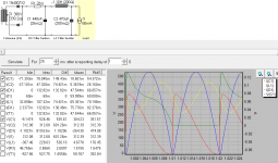
This is a choke input supply as the first capacitor is too small to affect the output voltage. With those two components in place, the diode current begins smoothly and continues over the full (half) cycle.
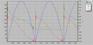
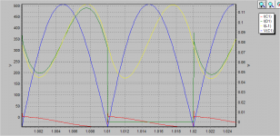
With the damping significantly reduced (fig.1) the diode current spikes and rings, then ceases earlier than previously. With the capacitance significantly reduced, the diode current is non-zero when cut off.
With the damping significantly reduced (fig.1) the diode current spikes and rings, then ceases earlier than previously. With the capacitance significantly reduced, the diode current is non-zero when cut off.
Attachments
- Status
- This old topic is closed. If you want to reopen this topic, contact a moderator using the "Report Post" button.
- Home
- Amplifiers
- Power Supplies
- PSU design check