Hi all,
In PSU Designer II I have simulated 3 configurations:
1) 220uF / 5H(102 ohms) / 220uF
2) 50uF / 2H(29 ohms) / 50uf / 2H / 50uF
3) 30uF / 1H(25 ohms) / 30uF / 1H / 30uF / 1H / 30uF
All 3 simulations use transformer with 295Vac output and bridge rectifier (4 x 1N5406). The output current is 143mA (for a stereo amp with KT88 set)
The results are:
1) output voltage 373V with 6mV P-P
2) output voltage 378V with 5mV P-P
3) output voltage 374V with 7mV P-P
So considering the results are identical, which configuration would be better (if any?) 2 things that I see different is the cost and the layout of the components. But if the cost and layout are not an issue which configuration would give better sound? I think if you have a lot of cells with smaller value components could create oscillations. If there is no issue regarding oscillations how about a configuration with a lot of cells (say 10 cells with 5uF / 0.2H). Would that work too?
Thanks,
Alex
OK so in PSU designer II I changed the current:
Value 1 is 50mA
Value 2 is 143mA after 5 sec.
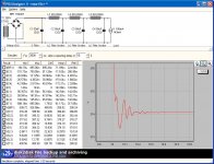
I don't really understand why the results are worse compared to no step but here it is:
1) 366V 7mV p-p
2) 372V 6mV p-p
3) 367V 8mV p-p
I don't know how to interpret these new results.
In the end I like to know if there are any negative effects in using multiple cells?
Thanks,
Alex
Value 1 is 50mA
Value 2 is 143mA after 5 sec.
I don't really understand why the results are worse compared to no step but here it is:
1) 366V 7mV p-p
2) 372V 6mV p-p
3) 367V 8mV p-p
I don't know how to interpret these new results.
In the end I like to know if there are any negative effects in using multiple cells?
Thanks,
Alex
Without the step, it is assumed that the current draw is constant, and of course power draw fluctuates according to music signal. Diode spike also can induce ringing in poorly damped LC filter.
To tame the ringing, you need to either increase the series resistance, increase the capacitance, or both to keep the values practical.
Also, you would want to to arrange the chokes in increasing inductance, and the capacitors in increasing capacitance. Play around with the values you would eventually get it.")
To tame the ringing, you need to either increase the series resistance, increase the capacitance, or both to keep the values practical.
Also, you would want to to arrange the chokes in increasing inductance, and the capacitors in increasing capacitance. Play around with the values you would eventually get it.
SE amp or PP, it does make a difference both in how critical supply transient response is and the amount of ripple you can tolerate on its output. In general a well damped step response is what you are shooting for. SE amps have very poor PSRR unless parafeed so ripple level becomes important.
You should look at the overall shape of the voltage, not the ripple. When the current draw changes does the voltage change smoothly or does it ring?alecu7 said:I don't know how to interpret these new results.
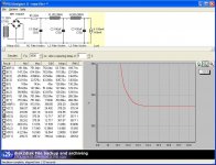
It's much better, but could be better. You would want a smooth curve.
Try decreasing C2, even if it'll be lower than C1 (this I am not sure and you have to try). If it doesn't work, you'll have to increase C3. Basically the smaller the middle cap and the larger the end cap the smoother will the curve be.
Try decreasing C2, even if it'll be lower than C1 (this I am not sure and you have to try). If it doesn't work, you'll have to increase C3. Basically the smaller the middle cap and the larger the end cap the smoother will the curve be.
- Status
- This old topic is closed. If you want to reopen this topic, contact a moderator using the "Report Post" button.
- Home
- Amplifiers
- Tubes / Valves
- PSU configurations for tube amp