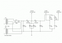
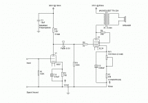
And for anyone interested in building this here is the PSU. One note though. I'm running this at 55mA bias on the output tubes because of the current limitation on the output transformers I'm using. If you can I would run the bias at 70mA on the output tubes. You will have to use a power transformer with a little higher secondary voltage in that case. The transformer represented in the schematic is a Hammond 372JX.
G
G
Attachments
Hi,
Gavin,
I would put the 1000µF on the 5687 cathode and vice versa.
Positron,
Very good remark, it happens to concur nicely with test run here locally in Western Europe.
When I first mentioned it here I met with some rather fierce opposition though...
Cheers,

Gavin,
I would put the 1000µF on the 5687 cathode and vice versa.
Positron,
Just some thoughts of my testing and experience.
Very good remark, it happens to concur nicely with test run here locally in Western Europe.
When I first mentioned it here I met with some rather fierce opposition though...
Cheers,
Hi,
Nothing really wrong here but why go so deep in the bass department when you know that the OPT won't pass it anyway?
Maybe I could just as have well said, keep the 470µF on the input but use no more than 220µF on the powertube...
IME it is not going to do transient response any good, making for a rather slow amp.
Cheers,
Wouldn't the 470uF on the 5687 give a -3dB point of around 1Hz? Did I do the math wrong...or the wrong math? Or is there something else coming into play that I'm not aware of here?
Nothing really wrong here but why go so deep in the bass department when you know that the OPT won't pass it anyway?
Maybe I could just as have well said, keep the 470µF on the input but use no more than 220µF on the powertube...
IME it is not going to do transient response any good, making for a rather slow amp.
Cheers,
Guys my recipe for designing a tube amp is simple and in your eyes probably leaves a lot to be desired. I have no idea what calculation you are talking about as far as the bypass cap on the 5687 goes. Maybe you would be kind enough to explain. I put the cap there strictly to lower the "ra". Or is it "Ra"? I put the rather large bypass cap on the output stage to maximize the bass extension as triodes are weak in this area. At least triodes in SE amps are. Haven't gotten around to PP yet. I assume the calculation is similar to the calculation for a coupling cap. Sometimes ignorance is a blessing and sometimes a curse.
G
G
Hi Frank,
I just wondered if there was reason to lower the -3dB point on the driver tube and raise it on the output tube. Now I see that you were just working with what G had already ordered.
G,
You probably have the correct equation. I use 1/ (2*pi*R*C) I think that's the correct one in this case. That's about as complicated as my math skills will allow at this point. I'm still having a tough time juggling all the variables in circuit design too, so you are hardly alone. I think it's a life-long thing..learning that is.
Thanks,
Tom
The more I learn, the more questions I have.
Hi,
Yes, it just seemed odd to me...In the end you end up NOT doing any maths but go by what you've seen done before I reckon??
When in doubt I do resort to the maths...
Guess I'm not a fly by numbers kind of person...
Yes, that and Ohm's law is all you ever need most of the time.
One more yes, it makes it almost as fascinating as horseback riding ...
Cheers and be patient while you do the ropes...it's well worth the
effort.

Now I see that you were just working with what G had already ordered.
Yes, it just seemed odd to me...In the end you end up NOT doing any maths but go by what you've seen done before I reckon??
When in doubt I do resort to the maths...
Guess I'm not a fly by numbers kind of person...
I use 1/ (2*pi*R*C) I think that's the correct one in this case.
Yes, that and Ohm's law is all you ever need most of the time.
I think it's a life-long thing..learning that is.
One more yes, it makes it almost as fascinating as horseback riding ...
Cheers and be patient while you do the ropes...it's well worth the
effort.
Hi,
In this case R = Rk the cathode resistor.
Exactly.
Cheers,
I assume that when using this formula for calculating a bypass cap you would use the total R of the tube and cathode resistor. Correct?
In this case R = Rk the cathode resistor.
since that's what's being bypassed.
Exactly.
Cheers,
> you would only use the actual resistor in the equation, since that's what's being bypassed.
No, it is also bypassing the tube's cathode impedance!
Rk is the same as 1/Gm, transconductance. I don't have a spec-sheet handy, but for this type tube working about 50mA I would guesstimate about 200Ω to 300Ω.
In most cases of self-bias, you will find that the cathode resistance is around half of the necessary bias resistor.
Take the low guess of bias-resistor and cathode impedance, 500Ω and 200Ω. Parallel them. 143Ω.
Ignoring load effects, for 17Hz response with 143Ω I would grab a 70µFd cap.
Since weak bypassing raises plate impedance in the bass, where load (transformer) impedance is falling, a "just big enough" cap will sometimes give a bass-bump, and sure is not helping damping. And -3dB at 17Hz is barely "hi-fi". Also the "grunge" of electrolytics is less if you over-size them. And electro caps at this voltage level are not that expensive. I would look at at least 4 times "just enough" or 280µFd, something like that. 220 or 1,000 should be fine.
Going back to the power supply on page 2 message 21: without doing an analysis, my pants-seat guess is that 32µFd - 100Ω - 64µFd may not be enough filtering for a transformer-loaded triode with no feedback. You could get a little less hum and much less buzz if you split the 100Ω into two 50Ω resistors and moved one of the caps: 32µFd - 50Ω - 32µFd - 50Ω - 32µFd. However 32µFd may not be enough supply bypassing for two channels, there will be some crosstalk. One way or another, I would use more capacitance.
- Status
- This old topic is closed. If you want to reopen this topic, contact a moderator using the "Report Post" button.
- Home
- Amplifiers
- Tubes / Valves
- Pros and Cons of this technique?


