Presuming the worst case scenario with absolutely awful simple silicon bridge rectifier without any snubber (just a transformer and GBP bridge rectifier)
a) How much will the resulting interference, caused by the interaction of transformer secondary with the bridge rectifier, be present in the output signal of the power amplifier at usual home listening levels (0,5W)?
b) How much will that interference influence IM distortion of the power amplifier at usual home listening levels (0,5W)?
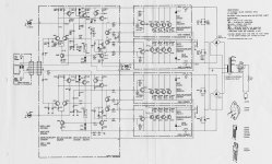
I think the Adcom GFA-555 power amplifier, designed by Nelson Pass, meets your specifications.
Its rectifier is a plain ordinary KBPC1004 silicon bridge rectifier assembly (datasheet) and there are no snubber(s) connected to the rectifier and/or to the trafo secondary.
Filter capacitance is a single 15,000 uF (100V) capacitor per rail, with a 39K 2W bleeder resistor to discharge it when power is shut off.
Since it seems to fulfill your requirements, you could use the Adcom GFA-555 as a testbench to measure the data you seek. Maybe you'll get lucky, and discover that an audio reviewer has already made the measurements and published the results. Or perhaps you'll need to measure it yourself. Either way, I'm sure you will enjoy the process.
A couple of "oh by the way" observations:
Interestingly, the Adcom GFA-555 has NO output inductor. Also there is NO "Zobel network" , sometimes called "Boucherot cell" , on the output. Nelson Pass and/or Adcom, didn't feel they were necessary.
However there is an RC snubber connected in parallel with the ON/OFF switch that feeds AC mains power to the amplifier.
thread
_
Attachments
Last edited:
Depends on your speaker. Some will ignore it, some may cause IM distortion.
Do an experiment, inject 1 mhz ringing on a 20 khz tone. Use a scope to verify pass through to amp output. See if your microphone and spectral analyzer can see any change in the output of your speaker.
I would suggest a previous experiment if your name is ivan. Test your hearing, or have it tested. IMHO most males over age ten have already ruined their hearing above some frequency, with fireworks, firearms, motors, or loud music. My frequency top is 14 khz; beyond that is the constant whistling of tinitis. My best speakers roll off at 14.5 khz.
Most of my friends seem to be much more deaf than I am. They can't tell the difference between a *****y new ****** console piano promoted by salesman in a suit, and an excellent old Baldwin they gave away.
Another primitive amp with no zobel out is the Allen S100. The coils that trapped RF from field wiring were in the front/back volume control unit following. The ferite bead on output shown on the schematic is not present in the unit I'm repairing. It does pick up AM radio from the field wiring without the front/back unit.
Last edited:
The most relevant test would be to use Audio Precision System to measure distortion and noise with and without snubber at 0,5W level. Unfortunately, amateurs like me can not justify such expense.
I am not questioning the fact that there is resonant circuit ringing. I can clearly see the two Rigol screen shots in the RingNot pdf. I only want to know how much of it will find it's way to the output of amplifier. After all, we do not want to help companies to sell more C and R, and more expensive diodes. We want better sound.
We can clearly see under the microscope that there is parasites on our skin, bacteria and fungi. Does this mean that we should sterilize our skin. Of course, not. Only if pathologic condition develops we must intervene. (Even if we sterilize, it's only a question of minutes until bacteria are again on the skin. They are omnipresent. In real world there will always be many interference sources, not just resonant circuit ringing. The question is only how much of it we will hear.)
Likewise, we see that there is ringing but we need to remove it only if there is some big enough consequence at the output of amplifier. If the consequence is more or less negligible there is no point in "sterilization".
Then you may have a long wait before you learn the answer. Either (i) wait until you are able to obtain access to an Audio Precision measurement system, then perform the tests which interest you. Or else, (ii) wait until someone else decides to perform the tests which interest you, and publishes their results.
While you are waiting, you might decide to build some audio gear. During the build, you will decide whether or not to deploy countermeasures against transformer ringing. Perhaps you may even decide to install the countermeasures (at nonzero expense), listen to the audio gear for many hours, then remove the countermeasures and listen again, for many more hours. Finally, choose whichever option whose sound you like best.
While you are waiting, you might decide to build some audio gear. During the build, you will decide whether or not to deploy countermeasures against transformer ringing. Perhaps you may even decide to install the countermeasures (at nonzero expense), listen to the audio gear for many hours, then remove the countermeasures and listen again, for many more hours. Finally, choose whichever option whose sound you like best.
My point. This ringing happens 100 times faster than my ears can hear. I stopped caring about 20 khz in 1969 when the Army shot off the howitzer. Most guys here are probably worse than me. I might put a 10 ohm resistor in series with the .01 uf cap across my transformer out next time, might even up the .01 to .047. Pennies, but I don't expect any audible benefit. Being informed, I'll used cheap old convenient slow diode bridges rather than fast recovery, ultra fast, or schottky diodes that cause ringing problems (probably still inaudible). I do worry about the snaps I hear when a lightning bolt goes off nearby - probably lots of 1 mhz ringing after one of those impulse waves out of the transformer. .047 uf + 10 R might be good snubbing, but has to come in 1000 v ceramic variety to do any good on snubbing lightning caused power line surges.Likewise, we see that there is ringing but we need to remove it only if there is some big enough consequence at the output of amplifier. If the consequence is more or less negligible there is no point in "sterilization".
Spend your money on distortion controlled +- 3db flat frequency response time aligned speakers; there are audible differences there, even to me. Mine roll off ultrasonics by specification.
Last edited:
Hi Scott,
-Chris
You lost me completely there ...Like the desire to buffer everything all the time, what audible improvement does that bring besides perhaps less HF roll off?
-Chris
Clearly, a poorly understood area. BTW, you most definitely should buffer that connection!
Why? Because the cable and amplifier both have capacitance and it needs to be driven. Some BJT input stages have lower distortion driven from low impedances, input resistance notwithstanding. Then there is noise immunity. Electrical noise picked up by the wire is a high impedance, so the output impedance of the rest of the circuit forms a voltage divider. Lower the driving impedance and your ratio is a lot higher (= lower noise).
Finally, has anyone thought of the voltage levels seen in this leg of a typical audio system? Small but audible signals are phono cartridge levels folks. Phono preamps are carefully designed low noise stages with high roll-off. Amplifier inputs are not typically designed with the same care and attention to noise issues, and it is a flat response, no high rolloff to reduce hiss. Some amplifiers are clearly better than others. My bet is that a DIY chip amp isn't one of the better designs from a noise standpoint.
So in summation, we have a high impedance, tiny signal running through variable quality patch cords. Would you rather it be a low impedance signal, or a high impedance one?
-Chris
If the pot is at the amp end I can't think of an audible reasonif you have a low impedance preamp source, say 600 ohms, and a high impedance input power amp say >>10k, then why buffer?
Then that's called an integrated amplifier. The wiring from the volume control isn't shielded and you only have to drive the input stage of the amplifier.
Food for thought. In better integrated amplifiers, the volume control is still buffered.
Remember that what works and what you can get away with isn't always the proper way of doing things.
-Chris
Food for thought. In better integrated amplifiers, the volume control is still buffered.
Remember that what works and what you can get away with isn't always the proper way of doing things.
-Chris
all power amps that i build, i include a 100k pot at input, so that if user wants to input the source directly, he can...
so when the user wants to use a line amp, that pot is adjusted to max....
all inputs in my line amps i put a 220k terminating resistor and not leave the rca jacks hanging....
so when the user wants to use a line amp, that pot is adjusted to max....
all inputs in my line amps i put a 220k terminating resistor and not leave the rca jacks hanging....
Yes, all about compromises and pros and cons (to partially get back to the thread ") ) perhaps, with audio, "good enough" really is good enough and the added complexity of a technically better or right way serves no purpose but as a practical challenge. I have built a Doug Self preamp/tone control with a total of 30 op amps and it sounds great and I believe it measures very well too, it is a tool to me, serves a purpose but when I take it out of circuit and have just a pot before the power amp (no preamp) there is no audible degradation, no hum
) perhaps, with audio, "good enough" really is good enough and the added complexity of a technically better or right way serves no purpose but as a practical challenge. I have built a Doug Self preamp/tone control with a total of 30 op amps and it sounds great and I believe it measures very well too, it is a tool to me, serves a purpose but when I take it out of circuit and have just a pot before the power amp (no preamp) there is no audible degradation, no hum
) perhaps, with audio, "good enough" really is good enough and the added complexity of a technically better or right way serves no purpose but as a practical challenge. I have built a Doug Self preamp/tone control with a total of 30 op amps and it sounds great and I believe it measures very well too, it is a tool to me, serves a purpose but when I take it out of circuit and have just a pot before the power amp (no preamp) there is no audible degradation, no hum- Status
- This old topic is closed. If you want to reopen this topic, contact a moderator using the "Report Post" button.
- Home
- Amplifiers
- Power Supplies
- pros and cons of monolithic bridge rectifiers for power amp PS