My point was that the 'traditional' terms were named after what sample you returned, iow voltage feedback meant you took (a sample of) the output voltage and returned that as feedback, while if you sampled the output current you would call that current feedback. It had nothing to do with the impedance of the node to where you send the feedback.
True! True! 100% true!
")
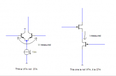
Those so called CFA are genuine VFB topologies , the difference
with a differential is just buffering of the return signal , nothing
that can be qualified as different on a technical ground.
The alleged low impedance of the inverting input of thoses "CFA"
doesnt hold since the transistor that buffer the said input in a differential
works in common collector , hence its output impedance is very low ,
in fact it can be even lower than the one provided by the FB network
in said "CFAs"...
100% correct. I hope bonsai learns from this....Finally!
Wahab, Michael, when you have a chance (if not already), please read through these Texas Instruments application reports:
http://www.ti.com/lit/an/sloa021a/sloa021a.pdf
http://www.ti.com/lit/an/sloa021a/sloa021a.pdf
After reading these do you will still believe that there's no difference, on technical ground, between VFA/VFB and CFA/CFB?
Hey, I don't really care one way or another, I just wanted to flag that the rest of the world has a different definition.
Once you start to study feedback and control systems you'll be confronted with the 4 topology definitions:
shunt - series feedback;
shunt - shunt feedback;
series - series feedback;
series - shunt feedback
where shunt stands for 'voltage' and series stands for 'current'.
Sorry if I rubbed you the wrong way!
jan
Yes we know all that. What is trying to be proven is that CFA's are not VFA's and I've put my case forward and I am going to leave it a that.
Pioneer were using what we term CFB topology in their amps which were sold on the market back in 1978. By CFB topology I mean the use of the diamond buffer inputstage. The amp in question is the MZ1 and a matching preamp the CZ1. If you view schematics of these amps and preamps youll find that the inputstage and transimpedance stage is represented as a block diagram and everything else is shown. The obvious reason was to conceal the circuit. They had problems obtaining USA patents (I wonder why when the circuit was novel) but finally did manage in 1983 although their first request was entered in 1980. How Elantec and Comlinear were able to patent the exact same circuit just 3 -4 years later I dont understand. Either the examiners failed to find the prioir art or through some tecnicality. It was indeed the Japanese that came up with the circuit.
What is also interesting is that some time after the Pioneer came on the market Harmon Kardon also released a amp featuring such topology. Here no fully reliable schematics are available but it seems to be a very similar design to the pioneer. Its difficult to establish whether it was independently developed or developed from the pioneer. This Harmon Cardon is in many circles regarded as the best amp ever produced by them.
Thanks for that Manso - very interesting indeed.
The reason the cmfb designs sound better is this: The same amount of feedback applied to all frequencies makes the distortion character the same at all frequencies. You do not hear the low-mid sound different character than the high freqs. The distortions harmonic structure is the same everywhere.
Thx-RNMarsh
Thx-RNMarsh
"Expressions VFA and CFA should apply to amplifiers where it is either the output voltage or the output current which is under control, and should not describe the way the feedback is achieved [if we admit that the feedback applied to the emitter(s) of the input BJT(s) is of current nature which is fundamentally wrong]"
You are forgetting what the middle letter stands for: feedback
We are talking about the feedback quantity and not the output quantity that is being controlled.
Voltage output amplifier
Current output amplifier
Voltage feedback amplifier
Current feedback amplifier
Get it?
You are forgetting what the middle letter stands for: feedback
We are talking about the feedback quantity and not the output quantity that is being controlled.
Voltage output amplifier
Current output amplifier
Voltage feedback amplifier
Current feedback amplifier
Get it?
The reason the cmfb designs sound better is this: The same amount of feedback applied to all frequencies makes the distortion character the same at all frequencies. You do not hear the low-mid sound different character than the high freqs. The distortions harmonic structure is the same everywhere.
Thx-RNMarsh
It is easy to design a VFB amplifier with very high open loop gain and then flatten it using local VAS feedback and you can have the same case. I am not sure that this is the reason for better sound (if CFB sounds better??), I made my TT amp with both type of open loop gain and could not hear any difference(but I don’t have golden ear).
Damir
Wahab, Michael, when you have a chance (if not already), please read through these Texas Instruments application reports:
http://www.ti.com/lit/an/sloa021a/sloa021a.pdf
http://www.ti.com/lit/an/sloa021a/sloa021a.pdf
After reading these do you will still believe that there's no difference, on technical ground, between VFA/VFB and CFA/CFB?
Sorry, the first reference should be:
http://www.ti.com/lit/an/slva051/slva051.pdf
The reason the cmfb designs sound better is this: The same amount of feedback applied to all frequencies makes the distortion character the same at all frequencies. You do not hear the low-mid sound different character than the high freqs. The distortions harmonic structure is the same everywhere.
Thx-RNMarsh
Richard,
That's an interesting point. So, what are also saying is that the open loop gain is, therefore, the same for all frequencies. Yes?
"Expressions VFA and CFA should apply to amplifiers where it is either the output voltage or the output current which is under control, and should not describe the way the feedback is achieved [if we admit that the feedback applied to the emitter(s) of the input BJT(s) is of current nature which is fundamentally wrong]"
You are forgetting what the middle letter stands for: feedback
We are talking about the feedback quantity and not the output quantity that is being controlled.
And that is the change that has occurred. Over most of the last century, we WERE talking about the quantity that was controlled. And in feedback and control theory, we STILL do. That makes sense. Because if you make it refer to what you feed back, THEN you better define what is current, what is voltage. Is a feedback signal of 1mA and 5V a current or a voltage? How about 10mA and 6V? Or 100uA and 2V? See what a mess you get yourself into forgetting what it was all about in the first place?
jan
Better to say it twice;?..
Thanks for the litterature , anyway.
In the case where the positive input of an opamp is grounded (classical inverting voltage amp), is that VFB or CFB? The inverting input terminal appears to be a low impedance because you pump current in, but the voltage doesn't move much. What about the JLH design from 1969? Do you call that CFB just because the feedback connects to the emitter?
How do these statements correlate to your definition?
If you short the output of a VFB amp, the feedback goes to zero. The amp tries to increase the current until some limit is reached or smoke is released. Normal feedback occurs when the load is an open circuit.
If you short the output of a CFB amp, the feedback remains normal such that the output voltage is limited and a safe current flows in proportion to the input. If the load is an open circuit, the output slams the rails.
In a circuit like the JLH where input and feedback meet in a single ended stage, more even order harmonics are created. The differential input stage tends to cancel even harmonics if both outputs are summed like in a current mirror.
Wahab, Michael, when you have a chance (if not already), please read through these Texas Instruments application reports:
http://www.ti.com/lit/an/sloa021a/sloa021a.pdf
http://www.ti.com/lit/an/sloa021a/sloa021a.pdf
After reading these do you will still believe that there's no difference, on technical ground, between VFA/VFB and CFA/CFB?
I read those references a long time ago, and, of course, there're differences between VFAs and "CFAs": forward path gain, slew rate, etc.
However, my contention is that "CFAs" are, in fact, nothing of the sort, and are merely deeply compromised VFAs.
This because of the deterioration in perfomance that accrues, in audio terms, when you use a common emmiter amplifier to subtract the feedback voltage from the input voltage, instead of buffering said feedback voltage from the input transistor's emmiter with an emitter follower. The later combination gives rise to a differential pair.
Please ask Jan Didden for a copy of Cherry's paper on feedback amplifier configurations for the correct way to analyse the so-called "CFA".
Last edited:
I've built both VFA's and CFA's amplifiers and they both have their merits and shortcomings.
I've built both types (2 VFA's and 2 CFA's recently) and there's nothing flawed about the CFA. Of course, if you want single digit ppm distortion (why? Speakers are orders of magnitude higher than this) then build VFA's but I am not going to take a single dimensional approach to amplifier design.
Luckily there are more options for amplifier designers than blameless VFA!
Luckily there are more options for amplifier designers than blameless VFA!
Well said
For some people "Blameless" is end of the world.
In the case where the positive input of an opamp is grounded (classical inverting voltage amp), is that VFB or CFB? The inverting input terminal appears to be a low impedance because you pump current in, but the voltage doesn't move much. What about the JLH design from 1969? Do you call that CFB just because the feedback connects to the emitter?
How do these statements correlate to your definition?
If you short the output of a VFB amp, the feedback goes to zero. The amp tries to increase the current until some limit is reached or smoke is released. Normal feedback occurs when the load is an open circuit.
If you short the output of a CFB amp, the feedback remains normal such that the output voltage is limited and a safe current flows in proportion to the input. If the load is an open circuit, the output slams the rails.
In a circuit like the JLH where input and feedback meet in a single ended stage, more even order harmonics are created. The differential input stage tends to cancel even harmonics if both outputs are summed like in a current mirror.
Loudthud, you are talking about 2 different things here. Separate voltage and current feedback from voltage output and current output amplifiers. Maybe it's clearer if we say voltage defined or controlled output vs current defined or controlled output. This is not the same as voltage or current feedback.
You can use VFA or CFA to make a voltage or current defined output amplifier. One is about the output controlled variable and the other about the way the feedback works to deliver the controlled output.
I thought a bit more about this discussion, and I realised that many here feel this should be called 'current feedback' because there is appreciable current flowing into the feedback node. But it should be clear that that is not the case except for some error current due to finite feedback!
If there would be infinite feedback (implying infinite loop gain) the current in to the feedback node would be exactly zero.
Reality is different of course, but let's put some numbers to it.
See the circuit below, a gain of 10 feedback amp with an AD844. Let us assume the open loop gain at 1kHz is 60dB. Then, with the given values, what would be the current into the feedback node? The numbers are 'easy' so you can compute it from the top of your head easily.
jan
Attachments
I thought a bit more about this discussion, and I realised that many here feel this should be called 'current feedback' because there is appreciable current flowing into the feedback node. But it should be clear that that is not the case except for some error current due to finite feedback!
What's sauce for the goose... Same argument of course applies to 'voltage feedback' - the only voltage present at the -ve input node (inverting configuration) is the error voltage. With infinite open loop gain, there is precisely zero voltage being fed back.
Precisely; a completely arbitrary distinction.
In the example of the AD844 I showed above, the 'current feedback' is a whopping 470nA, see attached sim.
The DC offset current btw is about the same magnitude.
jan
In the example of the AD844 I showed above, the 'current feedback' is a whopping 470nA, see attached sim.
The DC offset current btw is about the same magnitude.
jan
Attachments
Last edited:
- Status
- This old topic is closed. If you want to reopen this topic, contact a moderator using the "Report Post" button.
- Home
- Amplifiers
- Solid State
- Pros and Cons of current feedback amplifier.