Are you sure about the operating conditions for the 6SC7 voltage amps? I have a hard time believing it will swing the required voltages. What's your assumed current and Vgk?
I'm also having trouble understanding why you'd use a cascode in the first stage for such a wussy voltage gain. I don't think that the bandwidth you're expecting is correct- I get more like 70kHz f3.
There's a bunch of more minor things, but I'll pick at the big issues first.
I'm also having trouble understanding why you'd use a cascode in the first stage for such a wussy voltage gain. I don't think that the bandwidth you're expecting is correct- I get more like 70kHz f3.
There's a bunch of more minor things, but I'll pick at the big issues first.
Current on the 6CS7 (NOT 6SC7- I made that mistake myself... here's the one I'm using: http://www.nj7p.org/Tube4.php?tube=6cs7 ) on the LTP (using the smaller of the two triodes in the tube) is about 4.5ma. According to the sim, I'm showing like 17v negative bias between cathode and grid. That, multiplied by 8 gain, gives about 135-140v swing negative, before the tube goes to grid current. By my calculation, I need about 100-130v to go full-output (60w) on the outputs (400v swing at the output transformer from rest) depending on the actual gain of the output tube. Also, remember that only POSITIVE output will count... and I've got at least about 150v on the anode resistor at idle, IIRC... that should cover positive voltage swing...
SY, what input drive impedance are you assuming to get 70KHz? I'm assuming nothing but the 330K+47K input load (that's the HIGHEST impedance the input grid could EVER see, even with an "infinite impedance" driving it, which should be the absolute worst case for bandwidth)... and the program says that bandwidth (driving the input of the 6CS7, about a 550K load) is still "greater than 1MHz")...
As for the gain- that's about all I could get, with an un-bypassed cathode resistor (so I can inject feedback from the output). With a cathode bypass cap, the gain goes up to like 150+, easy...
I don't know why I'm having so much trouble with TubeCad apparently... but I get the SAME results on EITHER of the two computers I'm using (one is an old P2-266 and the other is a Celeron 700 machine) that I use... I'll get to the bottom of this, I swear!!
Regards,
Gordon.
SY said:One more thing- why use such a low mu tube? Something like a 6GF7 strikes me as a better choice.
6CS7 can handle 500v on the plate, the 6GV7 only like 300 or 330. I looked at 6DR7s, 6GF7s and such, but the 6CS7 was the only one that had enough "B+ tolerance"...

While I'm writing- I was thinking, a few minutes ago, about something I read on TubeCad a little while back- using a pentode input tube in "ultra-linear" mode, by driving the screen of the pentode from a triode cathode follower, with the input for the cathode follower having its AC voltage voltage-divided from the output voltage of the pentode (IOW, using a cap and a couple of resistors, drive the grid of the cathode follower with full DC voltage from the pentode, but voltage-divide the AC voltage to like half). Anyone ever tried that in practice? I like the idea of keeping the output impedance lower, but having close to normal pentode gain... that could make a neat substitute for the cascode (and be able to swing more AC voltage, at a lower NET DC voltage fed to the next stage, compared to the cascode)...
Regards,
Gordon.
The 6GF7 (as an example) first section could be run with a CCS load at 2.5mA; with -4V between grid and cathode, the DC plate voltage is 350V. Dissipation is also well within margin. You have plenty of room to swing the 150V peak if your B+ is high enough. And that should get you a gain of nearly 30dB on each side of the LTP. Using a ruler on the curves, it appears that you'll have something like 2-3% 2nd harmonic (which cancels). Not bad at all. Get some decent gain out of the first stage (or cascade two LTPs) and now your talkin'.
OK.
Maybe I'm missing something fundamental here.
When the tube datasheets say "max plate voltage", I'm taking that, for most tubes, to mean the MAX voltage the tube should see for any part of its operational cycle. I know some output tubes are different... but if you look at them (say, the 6JB6), they have a MAX PEAK voltage figure listed as well... usually something in the few-KV range. But, with small-signal tubes, I take the plate voltage as the max... if that isn't right, then boy, I've been wasting a LOT of time looking for high-voltage tubes!!
SY, I plugged in that alignment for the 6GF7... and it looks like its IDLING at a plate voltage of about 318 volts. When that thing swings negative input bias, it looks like it's going to go WAY over the 330v max plate voltage of that tube, almost immediately... will this be a problem?
Also, there's another problem- the input DC grid voltage is only 3V. I need a MINIMUM DC input grid voltage of probably 60 volts, to make the Mulllard-style direct-coupled input (plate of the input tube coupled with the grid of the LTP without a coupling cap- getting rid of that cap was one of the FUNDAMENTAL things I wanted to do, to improve LF stability). Probably 100V DC grid voltage on the input of the LTP would be better. However, I've only got 550V rail voltage to play with. Hence, my alignment with the 6CS7... it gave me 135v swing. about 96v DC grid voltage, 4ma current... on that 550v rail. And the tube never sees over 500v on the plate (idle plate voltage is right at 300v)...
I know some of this might sound like stupid questions... but you gotta learn this stuff SOMEWHERE... and it's better to risk seeming stupid, and ask these questions now, rather than blow up some hard-to-find parts, and REALLY feel stupid then...
Thanks...
Regards,
Gordon.
Note that on the datasheet for the 6GF7, the max voltage is listed as "Max DC voltage." That's true of nearly every audio tube. Otherwise, transformer coupled output stages would have to be run at half their voltage. The peak voltage thing is usually a spec for sweep tubes, since they're used in HV pulse operation.
Remember, when we talk about grid voltage, it's not grid-to-ground, it's grid to cathode. You don't need 60V grid to cathode! What you need is sufficient bias so that the tube can swing the required voltage at its plate without running into grid current. For a tube with a mu of 60 and a required swing of 150V peak, that means 2.5V bias minimum.
Remember, when we talk about grid voltage, it's not grid-to-ground, it's grid to cathode. You don't need 60V grid to cathode! What you need is sufficient bias so that the tube can swing the required voltage at its plate without running into grid current. For a tube with a mu of 60 and a required swing of 150V peak, that means 2.5V bias minimum.
Hi Gordon and SY
In the schematic the driver and output stages are designed to be driven from the same B+. I understand it from the practical point of view (one supply), besides that it is nice to have high voltage available to provide headroom for a lot of driver capacity...BUT, as the output stage works in class B how will the driver stages react to the sags in the PS? Or are you planning to use a zero output impedance PS?
A related question...if one uses a separate B+ for the output tubes, how well regulated should it be? SY, what are you using in your 6LF6 amplifiers (I know it's about 800VDC, but not how you get to it)?
Many thanks, Erik
All good points. The regulation of the output stage becomes an interesting issue because of the high power and large current variations. That was probably the weak point of my big amp. The supplies were pretty simple, just big honkin' power transformers and CLC filters with a LOT of C.
For my input stages, I used separate supplies, and as a cheat, ran them bipolar. It's cheaper/easier to use +/-350V than 700V.
For my input stages, I used separate supplies, and as a cheat, ran them bipolar. It's cheaper/easier to use +/-350V than 700V.
I think this MIGHT actually WORK, this time!!
Changed a lot of stuff.
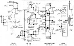
Went back to the 6SN7 for the LTP... it just could swing the voltage better, while being able to use the right DC grid voltage (relative to ground) to match with the output of the cascode (direct coupled).
With the 6SN7 as the LTP, that led me back to the 6BL7 for the cathode follower... no reason NOT to do that.
Still have the 6N30P as the input in cascode... but with a PARTIALLY bypassed cathode resistor. Got the gain up to 127...
The LTP now has a gain of about 8.77... with a CCS and some corrective anode resistors, balance should be pretty good. Bandwidth of the LTP should be around 210KHz... OK, I would think.
NOW I have enough gain, to get me around 20dB of negative feedback, AND still be at the same input sensitivity for full output as the Berning original circuit (about 1.5v input for full output). Depending on the outputs (which may give more than a gain of 3, according to my estimation), I MIGHT get even another few dB of open-loop gain, which might allow as much as 23-24 dB of total feedback.
My main trick I want to try, is as someone suggested (Douglas?), using a PENTODE as the CCS in the LTP. Looked around, and the 6EJ7 looked good... could handle the current, and had a suitably high plate resistance. HOWEVER- I would REALLY like some advice, in how to set up the pentode. I know I need 8ma of plate current... but EVERYTHING else is still unknown to me... what negative rail voltage on the cathode (I'd prefer to be able to use the same -200V as the negative rail on the cathode follower, if possible?), what positive voltage (assume probably something like 100v?) on the screen, what cathode resistor, what bias voltage (to set the resistors on the signal grid), etc... any assistance GREATLY appreciated!
I do thank all involved with their patience with me in this affair... I'm learning a bunch as I go along here.
Regards,
Gordon.
Changed a lot of stuff.
Went back to the 6SN7 for the LTP... it just could swing the voltage better, while being able to use the right DC grid voltage (relative to ground) to match with the output of the cascode (direct coupled).
With the 6SN7 as the LTP, that led me back to the 6BL7 for the cathode follower... no reason NOT to do that.
Still have the 6N30P as the input in cascode... but with a PARTIALLY bypassed cathode resistor. Got the gain up to 127...
The LTP now has a gain of about 8.77... with a CCS and some corrective anode resistors, balance should be pretty good. Bandwidth of the LTP should be around 210KHz... OK, I would think.
NOW I have enough gain, to get me around 20dB of negative feedback, AND still be at the same input sensitivity for full output as the Berning original circuit (about 1.5v input for full output). Depending on the outputs (which may give more than a gain of 3, according to my estimation), I MIGHT get even another few dB of open-loop gain, which might allow as much as 23-24 dB of total feedback.
My main trick I want to try, is as someone suggested (Douglas?), using a PENTODE as the CCS in the LTP. Looked around, and the 6EJ7 looked good... could handle the current, and had a suitably high plate resistance. HOWEVER- I would REALLY like some advice, in how to set up the pentode. I know I need 8ma of plate current... but EVERYTHING else is still unknown to me... what negative rail voltage on the cathode (I'd prefer to be able to use the same -200V as the negative rail on the cathode follower, if possible?), what positive voltage (assume probably something like 100v?) on the screen, what cathode resistor, what bias voltage (to set the resistors on the signal grid), etc... any assistance GREATLY appreciated!
I do thank all involved with their patience with me in this affair... I'm learning a bunch as I go along here.
Regards,
Gordon.
Attachments
Hmmm, I'd still want more gain from the driver but...
Let's start with the cascode. Your choice of that topology means that the power supply rail will have to be REALLY tight and clean- there's almost no power supply rejection. The RC circuit in the cathode could be replaced by an LED which will outperform the inevitably crummy electrolytic cap; it looks like your required drop is pretty close to a 1.7V red. The grid of the upper tube needs to be returned quite a bit more directly to AC ground. And RF ground, too, if you don't want a VHF transmitter.
The driver LTP can be simplified. If the CCS is worth a bucket of warm spit, the plate resistors (and grid resistors of the next stage) can be fixed and equal on both sides. Matched.
I'd just set the candidate CCS tube up on the bench to determine its operating conditions. Screen currents vary a lot. Of course, I probably wouldn't use a tube there anyway...
For the LED voltage-drop idea- I need more like 2.4 volts... but what, if anything, would be the problem with using a series combination of an orange LED (2v drop) and something nice like a .4V forward-voltage Schottky diode? That'd be pretty much exactly the right voltage...
Also, with diodes/LEDs... since there's NO switching involved here (it'll always be on), the normal issues with diode noise should not be any sort of an issue, right? I'd think that most ANY diode should work pretty well, right?
For AC-grounding the grids of the top cascode tube- John Broskie has a suggestion one of his pages at TubeCad, about putting caps in parallel with the resistors... which can be "ratioed" to cancel out some of the B+ noise, if done right. I'd think that might take care of both problems at one time?
One other thing- it was suggested that I change the grid-stop resistors on the cascode sections to 1K, instead of 47K. That was duly noted, and will be done...
As for the CCS tube- I actually went back and did the voltage drop calculations correctly, and determined that the 6EJ7/EF184 doesn't have enough B+ voltage handling (250V DC max across plate and cathode). So, I'm thinking something like a 6AU6... 300v B+ max... and a negative supply between -150 and -200 volts. Should get it in its "happy" range...
Thanks again, as always!
Started designing the power supply last night.
I had decided at the start, to give the output tubes/transformer stage it's own power transformer... to avoid having to drop a lot of voltages with resistors. So, all the "front end" stages are on a secondary power transformer.
As for power supply noise on the cascode and LTP stages- I used a 260-0-260 transformer with a full-wave voltage doubler, and a LCLC stage for the +700 for the LTP (something like 16 microvolts ripple/noise, as modeled in PSUDII), and an additional RC stage to drop the voltage to 550V for the cascode input stage (something like 60 NANO-volts of ripple/noise there). Since the input stage is Class A operation (all voltages/currents average to the SAME value no matter what the voltage swing), RC filtering for this stage should be just fine, AFAIK.
On the same 260-0-260 winding, I used a bridge rectifier across the 260-260 leads... which on the positive side, used a CLCLC filter, to give +350V high-current rail for the cathode follower driver stage (less than 100 microvolts ripple), and used a swinging choke LCLC filter to get the -200V for the cathode follower (about 100 microvolts ripple), with an additional RC stage hung from that to get -150v for the LTP CCS (with about 20 microvolts ripple). Again, I think an RC stage is fine for this, since it's driving a CCS (INHERENTLY constant current- no chance of droop).
For the outputs, I'm using a 400-0-400 465ma transformer with a full-wave rectifier and a CLCLC filter, to give +500V with less than 300 microvolts ripple, and regulation within 10% at full power (507V @ 200ma draw). Since I only need to swing 400v across each output tube for full power (60w), I'd think this should be fine... it can't get into the high-current-draw region of screen current.
SY, in your experience, would you think that 60 nanovolts ripple should be low enough for the cascode to work cleanly? According to my calculations, that's like well over 120dB down from rail voltage... I honestly can't think of why it shouldn't be fine. Of course, I'll have to build and test the power supply to make sure it works as calculated... but I have pretty high hopes that it should be fine.
Oh, and for those who are counting... that's two power transformers, EIGHT chokes and an output transformer PER AMP. Good thing I found a source for CHEAP surplus transformers and chokes!! The outputs will be new (Edcor), but the others are going to be like half of new prices, if that much... which makes it a LOT more practical!!
Regards,
Gordon.
I'd still actively regulate the input/driver if possible- it's easy, cheap, and will be nothing but good for LF stability. Noise is much less of an issue than impedance (as you surmise, the PSR of the LTP and cathode followers is very high and the noise is all common-mode), and regulators do a better job at DC and low frequencies.
May have found a better front-end...
What do you folks think about this:
5687 in cascode
745V B+ (I wound up with that for the LTP, due to transformer choices... a little higher still worked with that, without problems)
60K anode resistor
Cathode has orange LED (2.0v drop) in series with 30 ohm resistor
There's right at 10ma current through the stage, and gain is around 135. Bias voltage is about 2.38 volts or so. That should give me about 7.5 dB of voltage headroom on the front-end, between max output of the amp and input stage clip.
By raising the B+ of the first two stages to 745V, I also got an LTP output voltage of around 165V... which helps there, too. DC voltage carried between the cascode pentode and the LTP grid is about 139v, above ground, with about a -18.5V bias on the LTP (gain still around 8.7 there)...
The 5687 has a LOT less Cgp than the 6H30Pi... 4pf as opposed to 6pf. Quite a bit more bandwidth, with about the same gain...
Better still, the 5687 can be had CHEAP, compared to the 6H30P...
Regards,
Gordon.
Wholesale changes...
I'm frankly tired of banging my head against a wall, trying to get this thing to work with a LTP phase splitter. Obviously, this is not something that can easily be done with tubes that are commonly available, or with reasonable B+ voltages.
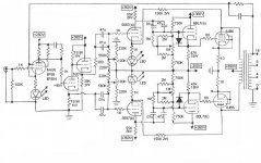
Decided to try something different... a concertina phase splitter with equal output impedance (cathode follower on the "top" side), and a second voltage amp stage... more like the original Berning EA230 configuration, but with steps taken to get around the limitations (voltage swing, bandwidth, gain) of the original design.
Once I decided to do this, I discovered FIRST off, that the 700V B+ rail is NO LONGER needed. I AM still going to use separate power transformers (one for the output, one for the rest of the amp), but I no longer need a voltage doubler on the second transformer.
Also, I was able to use MUCH MORE NORMAL tubes. Some of these changes might actually make the whole thing more linear than before...
I'm getting MUCH more voltage swing out of this, without the extreme B+ voltages (the most across ANY stage is 610 volts, for the second voltage amp and output cathode follower driver). Like, this thing MAY be able to put out as much as 80w/ch, depending on the behavior of the output tubes. I'm getting like close to 180v available at the screens of the output tubes, by the sims!
Also, the predicted bandwidth is MUCH better. Doing the Miller-capacitance calculations for likely alignments of a few of the different options for input pentode tube, I'm getting something like 450KHz... and the REST of the amp is "greater than 1MHz" according to TubeCad. And this time, the math actually agrees on paper! In this, the output transformer will be the only "wild card" as far as bandwidth is concerned... and I am pretty confident that I can take care of that situation with the Zobel on the input stage or the cap in the global feedback loop. If needed, I can always add a cap from a tube plate to the global loop, or try some of the things Bricktop did to "fix" the Heath W4... using the plates voltage on the output tubes as a "partial drive"/feedback for the second-stage voltage amps (see this thread on AudioKarma: http://www.audiokarma.org/forums/showthread.php?t=149678&page=2 )... stuff like that should be able to take care of things, I would think, at least in theory.
The astute viewer will notice that there are 3 LED's... in the cathode circuits of various stages... I will set whatever voltage drops I need (and whatever LED's I need to string together in series to do that) depending on whatever voltages I wind up needing, to properly "partially bypass" the cathodes of those tubes, to get the gain I need. That does seem like a much better idea than a resistor and an electrolytic cap!!
I don't have resistor values for the first stage yet; I'm planning to set it up for a gain of right around 100. Should be no problem for any of the tubes I'm thinking about. Gain of the cathodyne/concertina is of course just below unity (.95, IIRC), gain of the second voltage stage is about 13 or 14 (depending on what values I finally wind up using), the output driver cathode follower has a gain of about .9... and I'm assuming AT LEAST a gain of 2.5 from the output tubes (even in screen mode, they should do THAT much, if not more). If I wind up with lots of gain on the outputs, I'm going to drop back the gain on the first two stages a bit, so that total feedback (from the two loops, combined) is around 17-20 dB.
Wow... it's nice to actually have GAIN TO SPARE, at least in theory!!
So, any thoughts on this one????
Thanks!
Regards,
Gordon.
I'm frankly tired of banging my head against a wall, trying to get this thing to work with a LTP phase splitter. Obviously, this is not something that can easily be done with tubes that are commonly available, or with reasonable B+ voltages.
Decided to try something different... a concertina phase splitter with equal output impedance (cathode follower on the "top" side), and a second voltage amp stage... more like the original Berning EA230 configuration, but with steps taken to get around the limitations (voltage swing, bandwidth, gain) of the original design.
Once I decided to do this, I discovered FIRST off, that the 700V B+ rail is NO LONGER needed. I AM still going to use separate power transformers (one for the output, one for the rest of the amp), but I no longer need a voltage doubler on the second transformer.
Also, I was able to use MUCH MORE NORMAL tubes. Some of these changes might actually make the whole thing more linear than before...
I'm getting MUCH more voltage swing out of this, without the extreme B+ voltages (the most across ANY stage is 610 volts, for the second voltage amp and output cathode follower driver). Like, this thing MAY be able to put out as much as 80w/ch, depending on the behavior of the output tubes. I'm getting like close to 180v available at the screens of the output tubes, by the sims!
Also, the predicted bandwidth is MUCH better. Doing the Miller-capacitance calculations for likely alignments of a few of the different options for input pentode tube, I'm getting something like 450KHz... and the REST of the amp is "greater than 1MHz" according to TubeCad. And this time, the math actually agrees on paper! In this, the output transformer will be the only "wild card" as far as bandwidth is concerned... and I am pretty confident that I can take care of that situation with the Zobel on the input stage or the cap in the global feedback loop. If needed, I can always add a cap from a tube plate to the global loop, or try some of the things Bricktop did to "fix" the Heath W4... using the plates voltage on the output tubes as a "partial drive"/feedback for the second-stage voltage amps (see this thread on AudioKarma: http://www.audiokarma.org/forums/showthread.php?t=149678&page=2 )... stuff like that should be able to take care of things, I would think, at least in theory.
The astute viewer
will notice that there are 3 LED's... in the cathode circuits of various stages... I will set whatever voltage drops I need (and whatever LED's I need to string together in series to do that) depending on whatever voltages I wind up needing, to properly "partially bypass" the cathodes of those tubes, to get the gain I need. That does seem like a much better idea than a resistor and an electrolytic cap!!I don't have resistor values for the first stage yet; I'm planning to set it up for a gain of right around 100. Should be no problem for any of the tubes I'm thinking about. Gain of the cathodyne/concertina is of course just below unity (.95, IIRC), gain of the second voltage stage is about 13 or 14 (depending on what values I finally wind up using), the output driver cathode follower has a gain of about .9... and I'm assuming AT LEAST a gain of 2.5 from the output tubes (even in screen mode, they should do THAT much, if not more). If I wind up with lots of gain on the outputs, I'm going to drop back the gain on the first two stages a bit, so that total feedback (from the two loops, combined) is around 17-20 dB.
Wow... it's nice to actually have GAIN TO SPARE, at least in theory!!
So, any thoughts on this one????
Thanks!
Regards,
Gordon.
Attachments
- Status
- This old topic is closed. If you want to reopen this topic, contact a moderator using the "Report Post" button.
- Home
- Amplifiers
- Tubes / Valves
- Proposed screen-drive amp design... comments, please?