Hello all-
After considering a lot of options to match directivity to some SEOS24's I decided to follow Face's lead and experiment with some cardioid loaded woofers.
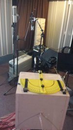
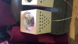
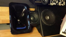
Grabbed a pair of dayton pa255-8 10" to experiment with...I figure if the directivity is coming from the cardioid loading, why not minimize C2C. So I made up the test boxes you see here, roughly following the layout used by gradient (seems like as good of a place to start as any).
One thing I noticed in cardioid woofer tests is that often not a lot of info/thought/data is going into what kind of material is used for the acoustic impedance. I know from the acoustics side (bass traps etc) and using the porous absorber calculator that gas flow resistivity vs thickness of material is not always intuitive. But after playing with PAC for a bit my thought was that GFR needs to be VERY high for an even absorbtion coefficient over the pass band, especially where mine is <500hz. Somewhere around 100k Rayls/m at 3-4 inches.
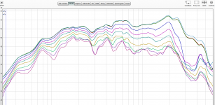
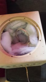
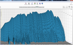
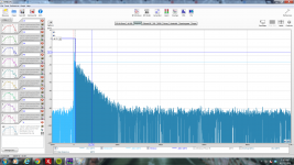
So time to test it! At first I put only two layers of denim carpet padding and the results were not good. Additionally with a 50hz sine you could hear audible chuffing noise at the ports. So with 4 layers of tightly packed pad, and fiberfill additionally packed in tightly here are the results. Also no port noise (I will cut roundovers on all of them anyway)...Also the waterfall is very clean for as good of a test as I can get there.
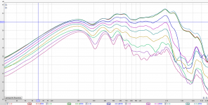
All the measurements were done inside, but the room there has a very clean ETC as there are essentially no specular reflections (diffusers) and there are many bass traps behind the eps diffusers. The measurements may not be perfect but IMO good enough to show that the cardioid loading is working...Also the waterfall looks very clean, it's difficult to draw too much from that measured inside but at least it shows no major stored energy. Walking around the box you can clearly hear the directivity of it.
The next step will be to finish and paint and pair them up with the SEOS24's Radian951Be's, if all goes well eventually I'll probably do new boxes for AE TD12's or something.
After considering a lot of options to match directivity to some SEOS24's I decided to follow Face's lead and experiment with some cardioid loaded woofers.
Grabbed a pair of dayton pa255-8 10" to experiment with...I figure if the directivity is coming from the cardioid loading, why not minimize C2C. So I made up the test boxes you see here, roughly following the layout used by gradient (seems like as good of a place to start as any).
One thing I noticed in cardioid woofer tests is that often not a lot of info/thought/data is going into what kind of material is used for the acoustic impedance. I know from the acoustics side (bass traps etc) and using the porous absorber calculator that gas flow resistivity vs thickness of material is not always intuitive. But after playing with PAC for a bit my thought was that GFR needs to be VERY high for an even absorbtion coefficient over the pass band, especially where mine is <500hz. Somewhere around 100k Rayls/m at 3-4 inches.
So time to test it! At first I put only two layers of denim carpet padding and the results were not good. Additionally with a 50hz sine you could hear audible chuffing noise at the ports. So with 4 layers of tightly packed pad, and fiberfill additionally packed in tightly here are the results. Also no port noise (I will cut roundovers on all of them anyway)...Also the waterfall is very clean for as good of a test as I can get there.
All the measurements were done inside, but the room there has a very clean ETC as there are essentially no specular reflections (diffusers) and there are many bass traps behind the eps diffusers. The measurements may not be perfect but IMO good enough to show that the cardioid loading is working...Also the waterfall looks very clean, it's difficult to draw too much from that measured inside but at least it shows no major stored energy. Walking around the box you can clearly hear the directivity of it.
The next step will be to finish and paint and pair them up with the SEOS24's Radian951Be's, if all goes well eventually I'll probably do new boxes for AE TD12's or something.
Attachments
Last edited:

Nice! What is impulse gating, 500ms? This long gating indoors does mask real directivity due to reflections and frequencies below Schroeder. I am sure that in reality directivity is stronger at >45¤ han these measurements show. How far did you measure? Looks like 10¤ steps. Please take the gear outdoors soon! Then measure also 90-180¤!
Low end directivity and response looks like dipole and there might be dipole null at 280Hz. The null is not as sharp as true dipoles, this looks very good for cardioid bass and mid up to xo around 1000 - 1500Hz
Low end directivity and response looks like dipole and there might be dipole null at 280Hz. The null is not as sharp as true dipoles, this looks very good for cardioid bass and mid up to xo around 1000 - 1500Hz
Great results.
Can you make a measurement in sealed box for comparison ?
Also I'd be nice to see some detailed pictures of layers of stuffing.
Oh man I wish I had time to make up a sealed box just for test purposes right now...
Not for the dayton drivers at least. I'm going to eventually try to replace all my guitar cabs with card boxes as well, so when I get to the JBL d120's I can compare them to the sealed boxes they are currently in. Paint is drying now, but I'll get some close ups of the stuffing as soon as I can.
Last edited:
Yeah. Such comparison could be VERY informative. Maybe you could just seal the holes with some tape or bitumen pads or smth else just for measurement?
Hmmm-
I think the whole test shows that GFR has to be very high in the first place. I don't think tape would have much effect at all. I do hear you, it's certainly not scientific without a control. I might be able to tape some MDF sheets over the ports...I'll give it a shot when I have a min to do more tests.
Nice! What is impulse gating, 500ms? This long gating indoors does mask real directivity due to reflections and frequencies below Schroeder. I am sure that in reality directivity is stronger at >45¤ han these measurements show. How far did you measure? Looks like 10¤ steps. Please take the gear outdoors soon! Then measure also 90-180¤!
Low end directivity and response looks like dipole and there might be dipole null at 280Hz. The null is not as sharp as true dipoles, this looks very good for cardioid bass and mid up to xo around 1000 - 1500Hz
Thanks. REW default- turkey L125 R500, and yes 90 degrees in 10 degree increments. I know these aren't perfect, but I live in the city so it's hard to get outside to measure...This particular room is a bit of an odd ball as well. It's (intentionally) very leaky, no drywall on the ceiling (just vapor barrier and loosely stuffed fiberglass in the attic), and literally a ton of 703 for bass traps. But yeah eventually I'll take the SEOS24's and these or a later iteration outside for further testing.
I was looking for ~12dB separation @90 degrees @500hz to match the SEOS24's. Everything will be with DSP (dlcp).
RyanC, for xo area investigation you can use eg. 9ms gating indoors with good results. I get lots of reflections at 12ms gating. Below 500Hz is most difficult to "see" clearly indoors. If you have saved those measurements, use IR button to change gating for each measurement. For quick check and to get in the ballpark you can use just 0¤ 30¤ and 60¤ measurements.
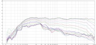
Here are some outside 180's with the boxes crossed over to the SEOS24/951Be @450hz. I worked with a bit more corrective eq, so these aren't raw, but give an idea of what the results can be as a total. Was hoping to have time to measure just these boxes, but it started getting cloudy and didn't want to risk it.
These are outside but unfortunately still in a (rather large) courtyard, so the gating is set to 40ms as the nearest reflective wall was about 25ft away.
Subjectively these are sounding very good in room. Enough so that I'm going to pursue this route on a larger scale (probably TD10M's for mids and low mids maybe TD15H also cardioid loaded). I think having both will allow me to make the best cardioid window for ea around 2 octaves...which makes 9 octaves of constant directivity with the 24's.
Definitely off-axis listening is much better than with my old setup.
Attachments
Ryan,Here are some outside 180's with the boxes crossed over to the SEOS24/951Be @450hz.
These are outside but unfortunately still in a (rather large) courtyard, so the gating is set to 40ms as the nearest reflective wall was about 25ft away.
What was the mic distance to the driver center in the various tests ?
Was the speaker rotated, or mic moved?
Art
Ryan,
What was the mic distance to the driver center in the various tests ?
Was the speaker rotated, or mic moved?
Art
About 3ft, the speaker was rotated, I put a large roll of poly-fill on the ground between the mic and the speaker to reduce the effect of reflections off the ground.
About 3ft, the speaker was rotated, I put a large roll of poly-fill on the ground between the mic and the speaker to reduce the effect of reflections off the ground.
Depending on the axis of rotation and the mic distance, your results may largely be reflecting inverse distance drop (six dB per doubling of distance) rather than cabinet directionality.
As an example, at 3 feet distance on axis in front of a 1.5 foot cubical cabinet, if the cabinet is rotated from the rear, the path length distance to the mic becomes almost double (3' +1.5' depth + a bit less than 1.5' to account for 1/2 the baffle and back width) for a 6 dB reduction from an omnispherical radiation pattern.
If the cabinet is rotated from the front, the distance around the cabinet would still add about 1.5' to the 3' distance, so SPL from an omnispherical radiation pattern would go down around 3 dB.
Rotated from the middle, level would go down around 4.5 dB, roughly half the reduction we about see in your plot below 100 Hz.
Last edited:
Oh man I wish I had time to make up a sealed box just for test purposes right now...
Not for the dayton drivers at least. I'm going to eventually try to replace all my guitar cabs with card boxes as well, so when I get to the JBL d120's I can compare them to the sealed boxes they are currently in. Paint is drying now, but I'll get some close ups of the stuffing as soon as I can.
The holes are onnly on horizontal sides left + right right? What if you just make two sides but solid and then clamp them over the enclosure? That should make it sealed enough for testing =)
Ryan,The boxes are 11" deep, I did my best to keep the center on and rotate around there (going to get a turn style for this in the future), would say the margin of error would be more like 1.5" of shifting off center.
Still not understanding which center you are rotating around (acoustic center, driver's cone center, center of box from front to back, voice coil location, etc.) but you seem to be ignoring the distance traveled from the driver's cone center around the box, which for a square 11" box would be a minimum of 22", and more in the vertical direction if the baffle is taller than 11".
If you were measuring at 10 meters, the difference of 22" is not much, but at 36" quite a large %. Even moving the test distance to 2 meters may make quite a bit of difference in your results.
Making accurate polar measurements is not easy, especially past 90 degrees.
Art
Hey Art-
I'm not sure I'm following completely, are you saying there is a reason why a 22" margin of error is the minimum for a speaker in a 11" wide box?
I rotated around the center of the box, which should be very close to the acoustic center as well as the front of the magnet is a little over 4" deep and the driver is flush mounted. The speaker was on a stand with a 5x5" platform on top so it would have fallen off if rotating on a 11" radius.
If the acoustic center stayed within a 6" diameter circle (estimating on the high side) the margin of error from 36" to 42" would be only 1.34dB...
Point taken that this is not *lab grade* accuracy and that I should have probably moved the mic back a bit further, my primary interest is inside 90 degrees.
Last edited:
- Status
- This old topic is closed. If you want to reopen this topic, contact a moderator using the "Report Post" button.
- Home
- Loudspeakers
- Multi-Way
- Promising loaded cardioid woofer test