Forgot to mention the need to clean the wires and bars with a solvent like wax and grease remover, before gluing. The bars should also be lightly sanded with a medium grit paper for better grab of the glue.
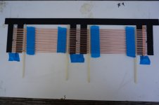
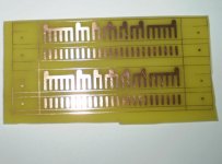
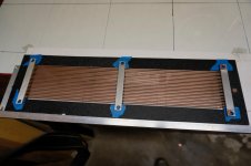
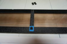
The cross bars are placed on the jig, marking their center with a dot from a sharpie. A strip of 1/4" copper conductive tape is placed on the bottom cross bar with enough to wrap around to the front just past the screw holes. Stick a little masking tape at the bar ends to prevent them from moving.(Attachment 1)
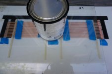
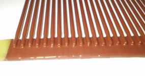
Since I was going to be gluing a lot of stators, I bought a 4 oz package of epoxy resin and hardner. However the only available type in that quantity at my local store was a 5 minute set time, so all the assembly parts needed to be ready as soon as the glue was put on. After mixing the epoxy, spread about a 1/4" wide thin bead across the bars, just past where the outside wires will land. However, no epoxy is used on the copper taped one. Now the wire assembly is placed on the cross bars, lining up the center dotted wires with the dot on the bars. Some of the wires may have become a little askewed so a few grommets are reapplied for proper alignment.(Attachment 2)
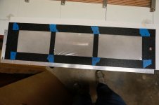
A piece of glass(preferably 1/8" or thicker) is placed on the top, carefully making sure everything is still lined up, but leaving the copper taped bar uncovered. Including keeping the wire aligned, the grommets also help any excess glue from adhering to the glass plate. A small can of paint or other similar object is put on top for a little weight. For clarity, I've put dots on the two outside wires on each side of the copper bar. Super glue is placed at these four locations so when the epoxy has dried and the assembly is lifted off, the bottom bar will be attached enough to keep it in position for soldering.(Attachment 3)
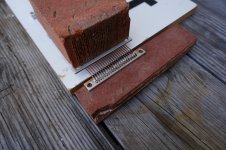
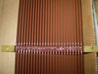
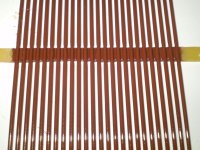
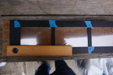
The bottom copper taped section is now placed on a flat fire proof object, in my case part of a split clay brick. One of our indispensable grommets is temporarily placed near the bar to hold the wires in position. Now two pieces of surplus aluminum bar(for heat dissipation) and a fire proof weight like part of a brick(to help the wires from moving when soldering) are positioned about one inch from the cross bar. It is now very important to remove the grommet before starting to solder, or it will become a permanent unwelcome addition to the stator. To make sure there would be a good flow, I lightly brushed a little flux on the wires and copper tape. Without my wife's knowledge, I used her creme brûlée mini butane torch as the heat source. You would think that the high heat would cause the copper tape to buckle or peal off, but it actually fuses itself to the aluminum.(Attachment 4) Soldering is very good for permanent continuity but it's a lot of extra work. The heat and flux also slightly discolor the wires so if you want to use a clear coat urethane for insulation, it will show. The next time(if) I might just epoxy all the bars and only use the conductive adhesive on the tape for continuity. Don't know.
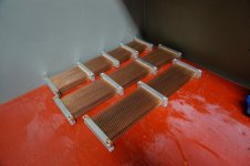
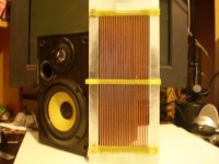
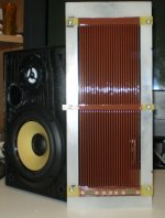
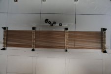
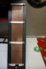
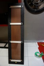
Once you get in the production mode, the stators start adding up. They actually look kinda neat.(Attachment 5)
For anybody who is still reading this, I hope it hasn't been too confusing so far. I know I get a little confused myself. They are a bit of work.
Bondsan
The cross bars are placed on the jig, marking their center with a dot from a sharpie. A strip of 1/4" copper conductive tape is placed on the bottom cross bar with enough to wrap around to the front just past the screw holes. Stick a little masking tape at the bar ends to prevent them from moving.(Attachment 1)
Since I was going to be gluing a lot of stators, I bought a 4 oz package of epoxy resin and hardner. However the only available type in that quantity at my local store was a 5 minute set time, so all the assembly parts needed to be ready as soon as the glue was put on. After mixing the epoxy, spread about a 1/4" wide thin bead across the bars, just past where the outside wires will land. However, no epoxy is used on the copper taped one. Now the wire assembly is placed on the cross bars, lining up the center dotted wires with the dot on the bars. Some of the wires may have become a little askewed so a few grommets are reapplied for proper alignment.(Attachment 2)
A piece of glass(preferably 1/8" or thicker) is placed on the top, carefully making sure everything is still lined up, but leaving the copper taped bar uncovered. Including keeping the wire aligned, the grommets also help any excess glue from adhering to the glass plate. A small can of paint or other similar object is put on top for a little weight. For clarity, I've put dots on the two outside wires on each side of the copper bar. Super glue is placed at these four locations so when the epoxy has dried and the assembly is lifted off, the bottom bar will be attached enough to keep it in position for soldering.(Attachment 3)
The bottom copper taped section is now placed on a flat fire proof object, in my case part of a split clay brick. One of our indispensable grommets is temporarily placed near the bar to hold the wires in position. Now two pieces of surplus aluminum bar(for heat dissipation) and a fire proof weight like part of a brick(to help the wires from moving when soldering) are positioned about one inch from the cross bar. It is now very important to remove the grommet before starting to solder, or it will become a permanent unwelcome addition to the stator. To make sure there would be a good flow, I lightly brushed a little flux on the wires and copper tape. Without my wife's knowledge, I used her creme brûlée mini butane torch as the heat source. You would think that the high heat would cause the copper tape to buckle or peal off, but it actually fuses itself to the aluminum.(Attachment 4) Soldering is very good for permanent continuity but it's a lot of extra work. The heat and flux also slightly discolor the wires so if you want to use a clear coat urethane for insulation, it will show. The next time(if) I might just epoxy all the bars and only use the conductive adhesive on the tape for continuity. Don't know.
Once you get in the production mode, the stators start adding up. They actually look kinda neat.(Attachment 5)
For anybody who is still reading this, I hope it hasn't been too confusing so far. I know I get a little confused myself. They are a bit of work.
Bondsan
Attachments
Haven't had much time in the last few days to tinker with the low frequencies, except for some tone control adjustments. I am fortunate to own more than one preamp. My main one is a highly respected(although vintage) preamp without any 'frequency' adjustments, but it's on the fritz now, so I am using my backup tuner/preamp with tone controls. Funny how many enthusiasts(including me) are resistive to using them....something more in keeping with a Philco radio console.
But the other night I decided to turn the bass control up, and all of a sudden there it was...clean bass. As with so many times before the opposite outcome of what I assumed occurred; I thought increasing the bass would cause more booming, but it didn't. I could actually hear the vibrations of the bass strings again. There was also a warmth to the sound that had been missing. On a few recordings I got goosebumps and the hair on the back of my neck stood up. That hasn't happened in a very long time. Of course it's not real low bass, but it gives me encouragement that there's room for more improvement. I do, though on fairly loud and dynamic passages, get occasional arcing in two diaphragm cells. Will have to work on that. If it is helpful at all for any analysis, the preamp boost the bass up to 6db at 100 hz. I have it up about 3/4 of the way. We have iPhones and iPads in the household, so will try to figure a good test app.
Hello Sy,
Will try to describe the plastic panel frames in the next few days. Probably similar to what's been built here before. Thanks for your interest.
Bondsan
Nice Build!!!
I glad to see more DIY'ers working on perfecting using TIG rod material for stators.
I had documented my smaller panels using this method that may have helped give you some ideas but sadly the websight that hosted the project has lost all of my pictures. :/
I used PCB materail for support and once I got a system flow down bulding them was a breeze and came out very accurate with just a few mil of tolerence.
Heating of the PCB was an issue at First since I warpped one pretty bad and had to replace it, the rest turned out perfect.
The next time I do it, I will use some brass hobby plate to solder the rods to.
Segmenting can be done very easily this way with only 3-6 rods per section.
jer")
I glad to see more DIY'ers working on perfecting using TIG rod material for stators.
I had documented my smaller panels using this method that may have helped give you some ideas but sadly the websight that hosted the project has lost all of my pictures. :/
I used PCB materail for support and once I got a system flow down bulding them was a breeze and came out very accurate with just a few mil of tolerence.
Heating of the PCB was an issue at First since I warpped one pretty bad and had to replace it, the rest turned out perfect.
The next time I do it, I will use some brass hobby plate to solder the rods to.
Segmenting can be done very easily this way with only 3-6 rods per section.
jer
Attachments
Last edited:
Hello Jer,
Good looking stats you have there. What type of wire insulation did you use, it looks very heavy-duty. Sorry to hear about your lost pictures. I should have taken more, but you don't always think about it at the time. I'm having to reenact some of the steps because of it!
Thanks for your comments.
Bondsan
Thank you for the compliment,
I used common off the shelf spray paints.
My method is documented starting here,
http://www.diyaudio.com/forums/plan...tric-coatings-fact-fiction-2.html#post2893839
jer
I used common off the shelf spray paints.
My method is documented starting here,
http://www.diyaudio.com/forums/plan...tric-coatings-fact-fiction-2.html#post2893839
jer
On to the plastic panel frames. I originally used polystyrene, but that stuff was a class in frustration; difficult to cut, with a terrible tendency to crack and shatter. Decided to make a trip down to the local(30 miles away) plastic store for some advice. The sales person there nodded his head in understanding my issues with the styrene and recommended ABS. It came in two colors-black or white, and three thicknesses-1/16, 3/32, and 1/8 inches. It's fairly stiff but pliable and is easy to cut; can be sawed with a fine blade or scored with a utility knife and snapped. Just about all my pieces were cut by scoring.
Three widths were used in construction: 1 1/2" for the top and bottoms, 1" for the sides, and 9/16 for the spacers. Basically I used these widths because I had a 1" metal ruler and a carpenter's square with 1 1/2 and 2" widths that could be used as guides for scoring. I think the next time I may increase the T and B to 1 5/8 or 1 3/4" for more clearance between the bias screw and wood frame.
It takes a little fine tuning of the 1" sides to determine their lengths, but once you have them, production mode sets in. I used 4 boxes to hold each specific panel size parts. The top and bottom, and the spacers were the same size for all panel frames so they were in separate boxes. 1/4 of of the 1 1/2" strips were drilled with a 3/8" hole for access to the bias connection.
The following examples will show different sizes of panels intermingled since I did not take enough pictures during the actual construction and had to reenact some of the steps with surplus parts. Please forgive if any or much of these procedures are already well known and used. But just in case:
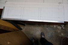
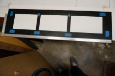
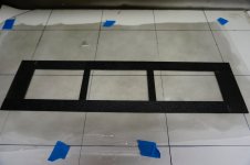
You begin by laying out a guide and template on a flat surface.(attachment 1) For strength you want to design over lapping joints between the front and back panel frames. That is, the front and back joints are opposite of each other.(exploded view attachment 2) Except for the 3/8" hole(missing in the picture) the two sides are are made exactly the same on the template, with inside smooth surface facing up(the ABS has one side smooth and the other textured). When the front side is flipped over and smooth sides are sandwiched together, you have opposite joints.
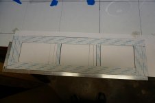
Ok, so once the panel strips are layed down on the template and aligned, a small piece of Scotch tape is put on each joint to hold it together just enough so it can be moved around a bit. For illustration purposes only I used blue masking tape.(attachment 3)
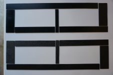
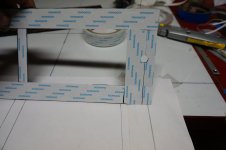
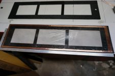
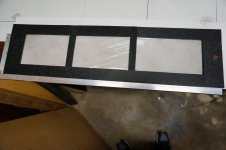
On earlier panels, I used silicone caulk/adhesive for gluing the mylar to the plastic, but this time I tried Scortape. This stuff is REAL sticky. I used 1" and 1/2" widths. Try to place the tape so it over laps the joints.(attachment 4) At this point the frames are beginning to get sturdier. The Scortape on the bottom side with the 3/8" hole needs to be cut out.(attachment 5)
Sorry, have to leave for a while. Will be back later.
Three widths were used in construction: 1 1/2" for the top and bottoms, 1" for the sides, and 9/16 for the spacers. Basically I used these widths because I had a 1" metal ruler and a carpenter's square with 1 1/2 and 2" widths that could be used as guides for scoring. I think the next time I may increase the T and B to 1 5/8 or 1 3/4" for more clearance between the bias screw and wood frame.
It takes a little fine tuning of the 1" sides to determine their lengths, but once you have them, production mode sets in. I used 4 boxes to hold each specific panel size parts. The top and bottom, and the spacers were the same size for all panel frames so they were in separate boxes. 1/4 of of the 1 1/2" strips were drilled with a 3/8" hole for access to the bias connection.
The following examples will show different sizes of panels intermingled since I did not take enough pictures during the actual construction and had to reenact some of the steps with surplus parts. Please forgive if any or much of these procedures are already well known and used. But just in case:
You begin by laying out a guide and template on a flat surface.(attachment 1) For strength you want to design over lapping joints between the front and back panel frames. That is, the front and back joints are opposite of each other.(exploded view attachment 2) Except for the 3/8" hole(missing in the picture) the two sides are are made exactly the same on the template, with inside smooth surface facing up(the ABS has one side smooth and the other textured). When the front side is flipped over and smooth sides are sandwiched together, you have opposite joints.
Ok, so once the panel strips are layed down on the template and aligned, a small piece of Scotch tape is put on each joint to hold it together just enough so it can be moved around a bit. For illustration purposes only I used blue masking tape.(attachment 3)
On earlier panels, I used silicone caulk/adhesive for gluing the mylar to the plastic, but this time I tried Scortape. This stuff is REAL sticky. I used 1" and 1/2" widths. Try to place the tape so it over laps the joints.(attachment 4) At this point the frames are beginning to get sturdier. The Scortape on the bottom side with the 3/8" hole needs to be cut out.(attachment 5)
Sorry, have to leave for a while. Will be back later.
Attachments
Continuing on, the tape backing is removed and the rear frame is placed on edge on top of the non-conductive side of a mylar sheet. I use old fashion graphite , but that topic is well discussed. The frame is let go falling on the mylar.(attachment 1&2)
The excess mylar is trimmed off and a 1/2" strip of copper tape is adhered to the now conductive side so it lines up with the 3/8" hole of the front frame. A 1/4" ring of tape is added around the perimeter.(attachment 3)
With the rear frame positioned back on the template, the front frame(with the tape backing removed) is carefully aligned and dropped on the back half.(attachment 4) A hole is now drilled through the center of the copper tape hole for the bias connection screw.(attachment 5)
Trying to explain all this makes it seem a lot more complicated than it really is. Next: attaching the stators.
Bondsan
Attachments
It is puzzling isn’t it? Any manner of mechanical, acoustical, or electrical tweaks on a speaker are accepted. But achieving the same or better results with simple line level equalization or tone controls is frowned upon. I’m sure there is some history there……I am using my backup tuner/preamp with tone controls. Funny how many enthusiasts(including me) are resistive to using them....
Sounds like you were successful in equalizing the low end of your ESL. Nicely done...the other night I decided to turn the bass control up, and all of a sudden there it was...clean bass. There was also a warmth to the sound that had been missing…If it is helpful at all for any analysis, the preamp boost the bass up to 6db at 100 hz. I have it up about 3/4 of the way. We have iPhones and iPads in the household, so will try to figure a good test app.

Many people have only heard the thin or lean sound of un-equalized ESLs, so they don’t realize fully what they are capable of.
Let me know if you are having issues locating a test app, I have a friend who uses Apple devices who could likely recommend a few.
I hear yaTrying to explain all this makes it seem a lot more complicated than it really is.
Thanks for your efforts in documenting your build.
Always interesting to see how others tackle different construction challenges.
Been busy with several non-fun DIY home projects.
Everything is just about ready for the stator/panel assembly. The wire stators have been given three coats of polyurethane.
The holes for the screws need to be marked and drilled. Since the ABS is black and textured, it's a lot easier to mark the holes by placing a small piece of masking tape( I use a bit of this stuff) approximately where the holes will be. Line the wire stator on the panel and mark the hole locations with a sharpie. (attachment 1&2)
Start by drilling 1/8" pilot holes and then finish with a 1/4" bit. While drilling with the 1/4" bit, the panel has a tendency to 'ride up' the the bit and become a propeller if you don't hold it down securely. I use a piece of wood with a large hole that I can place over the pilot hole and drill through it.(attachment 3)
Now 10/32 nylon screws and 1/16 spacers are placed through the front stator. The # 10 screws are a few sizes smaller than 1/4" to give a little leeway for alignment. The spacers are so when the screws are tightened, the panel will not bow.(attachment 4)
With the front side of the frame(the copper tape hole) facing down, the panel frame is laid on the stator and screws. 1/16" spacers are fitted on all the screws. For illustration, there is a some masking to better show the spacers.(attachment 5)
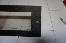
The rear stator is placed on the assembly and the nuts are just slightly tightened. A #8 brass washer is positioned in the front 3/8" hole with its smooth side against the copper tape. A 6/32 roundhead brass screw is inserted through the washer and hole. On the back side a brass nut is tightened just enough for a snug fit. A second brass nut is added for the bias wire connection. And now the stator assembly is finally finished, ready for installation on the wood frame!(attachments 6,7,& 8)
Bolserst,
Thanks for your comments, as always. I've downloaded a couple of audio apps but have not had the the time to tinker with them. Hopefully I'll have the time in a week or two.
Bondsan
Everything is just about ready for the stator/panel assembly. The wire stators have been given three coats of polyurethane.
The holes for the screws need to be marked and drilled. Since the ABS is black and textured, it's a lot easier to mark the holes by placing a small piece of masking tape( I use a bit of this stuff) approximately where the holes will be. Line the wire stator on the panel and mark the hole locations with a sharpie. (attachment 1&2)
Start by drilling 1/8" pilot holes and then finish with a 1/4" bit. While drilling with the 1/4" bit, the panel has a tendency to 'ride up' the the bit and become a propeller if you don't hold it down securely. I use a piece of wood with a large hole that I can place over the pilot hole and drill through it.(attachment 3)
Now 10/32 nylon screws and 1/16 spacers are placed through the front stator. The # 10 screws are a few sizes smaller than 1/4" to give a little leeway for alignment. The spacers are so when the screws are tightened, the panel will not bow.(attachment 4)
With the front side of the frame(the copper tape hole) facing down, the panel frame is laid on the stator and screws. 1/16" spacers are fitted on all the screws. For illustration, there is a some masking to better show the spacers.(attachment 5)
The rear stator is placed on the assembly and the nuts are just slightly tightened. A #8 brass washer is positioned in the front 3/8" hole with its smooth side against the copper tape. A 6/32 roundhead brass screw is inserted through the washer and hole. On the back side a brass nut is tightened just enough for a snug fit. A second brass nut is added for the bias wire connection. And now the stator assembly is finally finished, ready for installation on the wood frame!(attachments 6,7,& 8)
Bolserst,
Thanks for your comments, as always. I've downloaded a couple of audio apps but have not had the the time to tinker with them. Hopefully I'll have the time in a week or two.
Bondsan
Attachments
-
 Stator on frame to mark holes .jpg979.4 KB · Views: 140
 -
 Frame with tape and marks .jpg843.5 KB · Views: 123
 -
 Frame with holes and wood holder .jpg999.8 KB · Views: 115
 -
 Front stator with screws and spacers .jpg776.6 KB · Views: 131
 -
 Frame on top of front stator with screw and spacer .jpg985.3 KB · Views: 130
 -
 Rear view finished stator .jpg545 KB · Views: 130
 -
 Front view of finished stator .jpg479 KB · Views: 150
 -
 wood frame.jpg574.9 KB · Views: 159
Have finally had some time to fiddle with theses things again.
Since first firing them up, the right speaker always seemed to sound louder than the left. To make sure it wasn't just my aging ears causing the difference, I began to switch equipment around. What I found was whichever speaker had the bias supply return transformer, it was the louder one. I don't know if this is common or something peculiar in the design of the EMCO F40. As mentioned earlier, I bought a second F40 for future use, so figured now was the time to put it in service, so each speaker would have their own separate bias supply. Yep, that fixed it, and also cleaned up some of the wiring.
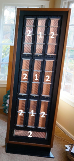
On to the segmentation modification. I wired in the 100K resistors that Bolserst recommended, and dang it really worked! I could sit just about anywhere with a decent image. However....at the cost of some resolution and excitement in the music; even after replacing the 2 ohm 'primary damping' resistor back to 1 ohm. A little too tame and polite for my ears. Started experimenting with various combos of Group 1 and Group 2 panels. As of now, the most pleasing compromise is having the two top outside panels as part of Group 1. Not as wide a 'sweet spot', but for the area where I do most of my listening it works very well. A very pleasing sound.
My latest tinkering has been to replace the Dyna OPT's two OPT's from an old Scott LK-72 amp. The Scott's have a ratio of 90:1, about double of the Dyna's, and seem to impart a little more snap and dynamics into the music. Not as dynamic as my Klipschorns, but very respectable, indeed.
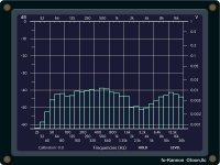
Below is the left and right speaker response taken with an iPad Mini app. I know it's not the most accurate, but it gives some idea of what's going with the the panels. They are at least 'semi' full range, and for most of the music I listen to, sound just fine on their own.
I do have the typical 'suck out' in the 3K range and wondering what can be done to prop it up. A Mini DSP equalizer?
As always, any comments or suggestions are greatly appreciated.
Still having fun, Bondsan
Since first firing them up, the right speaker always seemed to sound louder than the left. To make sure it wasn't just my aging ears causing the difference, I began to switch equipment around. What I found was whichever speaker had the bias supply return transformer, it was the louder one. I don't know if this is common or something peculiar in the design of the EMCO F40. As mentioned earlier, I bought a second F40 for future use, so figured now was the time to put it in service, so each speaker would have their own separate bias supply. Yep, that fixed it, and also cleaned up some of the wiring.
On to the segmentation modification. I wired in the 100K resistors that Bolserst recommended, and dang it really worked! I could sit just about anywhere with a decent image. However....at the cost of some resolution and excitement in the music; even after replacing the 2 ohm 'primary damping' resistor back to 1 ohm. A little too tame and polite for my ears. Started experimenting with various combos of Group 1 and Group 2 panels. As of now, the most pleasing compromise is having the two top outside panels as part of Group 1. Not as wide a 'sweet spot', but for the area where I do most of my listening it works very well. A very pleasing sound.
My latest tinkering has been to replace the Dyna OPT's two OPT's from an old Scott LK-72 amp. The Scott's have a ratio of 90:1, about double of the Dyna's, and seem to impart a little more snap and dynamics into the music. Not as dynamic as my Klipschorns, but very respectable, indeed.
Below is the left and right speaker response taken with an iPad Mini app. I know it's not the most accurate, but it gives some idea of what's going with the the panels. They are at least 'semi' full range, and for most of the music I listen to, sound just fine on their own.
I do have the typical 'suck out' in the 3K range and wondering what can be done to prop it up. A Mini DSP equalizer?
As always, any comments or suggestions are greatly appreciated.
Still having fun, Bondsan
Attachments
I have reworked over 10pr of ML panels.....stock the crossover 300-400hz to a 10" bass driver panels are 12"x46".....I can drive to full out put with 60 tube watts...sound is great
My Acoustat 1+1s an 2+2s can give 50-60 hz....in room 18'x25'...but I always add in a little from 2 ea 12" bass boxs ..... crossover.at about 50hz...
keep up the good work
My Acoustat 1+1s an 2+2s can give 50-60 hz....in room 18'x25'...but I always add in a little from 2 ea 12" bass boxs ..... crossover.at about 50hz...
keep up the good work
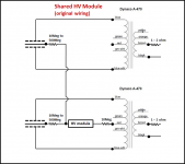
Scratched my head a bit over your comments, until I took a fresh look at the pictures from post#33 in your transformer thread.…What I found was whichever speaker had the bias supply return transformer, it was the louder one. I don't know if this is common or something peculiar in the design of the EMCO F40.
http://www.diyaudio.com/forums/plan...ct-transformer-bias-return-4.html#post4585618
You only had one wire from the HV module connected to the other speaker. In this case, the only way it was charging up is thru the leakage resistance between the transformer primary/secondary. This is a similar situation to what you had early on when you were connecting the HV ground to the 4 ohm tap(primary side) rather than the CT of the secondary.
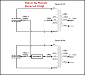
To correctly share one HV module, you need to connect both sides of the HV module to both ESLs.
Glad to see you are still having fun experimenting, and got to experience improved dispersion from segmentation… I wired in the 100K resistors that Bolserst recommended, and dang it really worked! I could sit just about anywhere with a decent image. However....at the cost of some resolution and excitement in the music; even after replacing the 2 ohm 'primary damping' resistor back to 1 ohm. A little too tame and polite for my ears…I do have the typical 'suck out' in the 3K range and wondering what can be done to prop it up. A Mini DSP equalizer?
Hmmmm…the large ‘suck out’ is not something I would call typical. In fact with finite length line source ESLs it is usually the opposite, where you have a mild peak in this frequency range. This would certainly explain why you felt you are losing some resolution and excitement since the dip is centered right in the presence region.
To help understand what is causing this, would it be possible to get measurements for one speaker with:
1) all the separate ESL panels driven together like you were originally using them (no resistors)
2) just the three “Group 1” panels driven together(no resistors, "Group 2" panels disconnected)
3) If possible, repeat 1) & 2) with both a 1 ohm and a 2 ohm resistance in series with the transformer primary.
Attachments
Your panels are looking very nice...Great Job !!!
One word of advice, as Bolserst shows in his drawing, Don't forget to use the resistors per Panel in your array.
I had found that it is possible for a section to hog the voltages from the other sections due to varying Leakage characteristics per section.
This will cause some of the panels to be louder than others or even not work at all if the sections are just directly connected parallel without them.
Besides reflections and microphone placement this could also maybe cause the suckout that you are seeing in your RTA graph (maybe) I had a very similar experience when I had three of my panels tied together in a small array.
Here is a post with a description of my discovery,
http://www.diyaudio.com/forums/planars-exotics/190716-esl-power-supply-question-2.html#post3788615
It is okay to directly connect the stator's together, But but Do feed each diaphragm separately with its own resistor from the bias supply source.
FWIW
jer
Bolserst,
Thanks for the correction and explanation. If you ever decided to write a book on 'ESL's for Dummies', you're welcome to use me as an example.
Will get to the measurement suggestions you made as soon as time permits, probably today or tomorrow.
Jer,
Thanks for the tip on using individual resistors for each diaphragm. Just ordered twenty 10 megs and will start experimenting when they arrive.
Bondsan
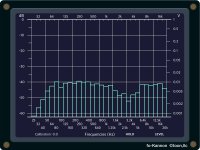
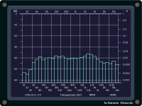
Measurement results.
Attachment 1: All panels with 1 ohm pad.
Attachment 2: All panels with 2 ohm pad.
Attachment 3: Center panels only 1 ohm pad.
Attachment 4: Center panels only 2 ohm pad.
Attachment 1: All panels with 1 ohm pad.
Attachment 2: All panels with 2 ohm pad.
Attachment 3: Center panels only 1 ohm pad.
Attachment 4: Center panels only 2 ohm pad.
Attachments
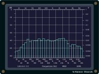
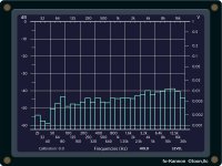
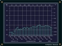
Those measurements look great, perfectly reasonable, no dips in sight.
Notice the measurements for just "Group 1" have a more extended HF response and are starting to show the inherent sloping response of an ESL line source. The object of segmentation is to add in more groups of panels as you go down in frequency at just the required rate to equalize the sloping LF response while retaining the better HF response and dispersion.
However, I am still puzzled about the dip you had previously measured...
Were these new measurements taken with the same setup(transformer, distance, mic/speaker room placement) as those from post#31 that showed a dip?
The reason I ask, is that when feeding additional panels thru resistors the response should never fall below the response of "Group 1" when measured by itself...which the dip definitely does. If measurement setup was identical, is there any chance that one or more of the "Group 2" panels got accidentally wired out of phase? (ie front and rear stator connections reversed)
- Status
- This old topic is closed. If you want to reopen this topic, contact a moderator using the "Report Post" button.
- Home
- Loudspeakers
- Planars & Exotics
- Progressively Sized Wire Stators