I admit to not having read those 50+ posts, but I will comment here nonetheless

Inductance is about magnetic fields. The inductance of a (resistor)coil can only be cancelled by an identical coil of reversed helical orientation if the magnetic field created by coil #1 is cancelled by the field of #2. In other words: the fields need to overlap. Unless the coils are on the same core (as in transformers) the fields will not overlap (completely) and will not cancel each other out. Any (theoretical) field cancellation will be highly dependant on the physical orientation of the coils and their proximity to each other.
So, in summary, you need two resistors, mirror imaged, occupying the same physical space.
I agree with you, with all my respect to the designer, and from my very own ignorance on any tube related discussion, that all ideas and improvements has to be welcomed. So I will be glad if we go ahead and try to. I'm in.I have just realised (am I right?) that the designer of this circuit is the person who advocated parallel opposed resistors. That rather calls into question the whole design, in my view.
Luckily, the builder (me) has a scopeMeanwhile, the original problem appears to be an oscillation (that should really be confirmed with an oscilloscope if the builder has one), but everyone is now stuck on the minutia of grid resistors and the finer practices thereof.
Are you saying that the discussion of grid resistors and the (presumably) problem of oscillation are not related? Aren't they, in fact, cause and consequence? Just saying, maybe I haven't understand your point correctly.... I'm sorry if it's that. I think that what you are proposing is to confirm an oscillation problem (if it can, and it can, be done) before blindly trying to place grind stoppers. Despite the fact that they "should" be there, anyway.So, let's go ahead. As I said, I have an scope I was given, and while far from being a master on using it, I know the basics on how to operate. Let me guess (and please, I ask you to correct me!), being a valve a current output device, the most convenient place to check for oscillation are across:
-1 ohm cathode resistors
-Output trafo secondary
Am I on the right track? What are we looking to find?
Hello Parafeed,I admit to not having read those 50+ posts, but I will comment here nonetheless
Inductance is about magnetic fields. The inductance of a (resistor)coil can only be cancelled by an identical coil of reversed helical orientation if the magnetic field created by coil #1 is cancelled by the field of #2. In other words: the fields need to overlap. Unless the coils are on the same core (as in transformers) the fields will not overlap (completely) and will not cancel each other out. Any (theoretical) field cancellation will be highly dependant on the physical orientation of the coils and their proximity to each other.
So, in summary, you need two resistors, mirror imaged, occupying the same physical space.
While heavily thanking you for your input, I would prefer if we continue this discussion on its own thread, for the sake of not making this thread more confusing than that it already is.
Luckily, the builder (me) has a scope
So, let's go ahead. As I said, I have an scope I was given, and while far from being a master on using it, I know the basics on how to operate. Let me guess (and please, I ask you to correct me!), being a valve a current output device, the most convenient place to check for oscillation are across:
-1 ohm cathode resistors
-Output trafo secondary
Am I on the right track? What are we looking to find?
When attacking any problem you start with the most probable cause, given the symptoms, and work to the least probable cause.
Grid resistors stop RFI from extraneous sources such as a close by radio station. The probability of that being the cause is low in my book.
Start with putting a resistive (not inductive) dummy load on the outputs. Radio shack sells some 20 Watt 8Ω resistors.
Apply power and connect the scope to the output at the dummy load. You can short the input of the amp to reduce extraneous hum.
Any oscillation may be at any frequency, so be sure to dial the timebase from low to high and see if you are getting a waveform. My first try when I built my amp had a very high frequency signal at high amplitude.
The high amplitude is what caused my power supply voltages to be different than what I expected. That fits your description, too.
If you see oscillation, disconnect the feedback to the output transformer or just move the feedback wire to the other side of the secondary winding and try again. You will also need to swap the ground on the secondary, too!
If this works, then swapping secondary leads changes the feedback from positive to negative polarity.
If it does not work, return the feedback wire to where it was, then use the scope to trace where the signal is coming from. Start at the input and work your way back to the grids of the output tubes.
However, my money is still on the reversed feedback polarity.
Last edited:
just saying, all components data should be checked if used in tube gearIf I'm not wrong, that grid resistor is only going to "see" 65v across it, isn't it?
Grid resistors also kill parasitic oscillation. The probability of that being the cause is quite high.Loren42 said:Grid resistors stop RFI from extraneous sources such as a close by radio station. The probability of that being the cause is low in my book.
Disconnect the NFB. Always debug a new valve amp with the NFB disconnected. Add grid stoppers. See what happens.
Hello Parafeed,
While heavily thanking you for your input, I would prefer if we continue this discussion on its own thread, for the sake of not making this thread more confusing than that it already is.
You are right regiregi22, disculpe.
Looking closer at the schematic, I have some more observations/questions, but let's focus on the first step: disconnect the feedback and see if the voltages stabilize. If they do, great. If they don't, check for oscillation with your scope and proceed further troubleshooting (like grid stoppers). Change one thing at a time to pinpoint the problem.
Thanks for the input, when when I ordered the BOM I made sure all resistor of the amplifier were at least as voltage tolerant as the higher voltage that the PSU outputs.just saying, all components data should be checked if used in tube gear
What I am going to do in that order would be:
-Check on the scope what I see
-Disconnect NFB, which is the easiest step
-If not solved, place grid stopper resistors
-Either of those should fix it, given that case, I would connect again NFB and put the grid resistors in place.
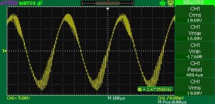
I just checked it on the scope. I forgot to tell you one symptom was that the output transformer makes a loud sound like tac-tac-tac-tac. When you turn the amplifier on, the transformer doesn't sound, but as soon as 10 seconds or so has passed (when tubes are getting hot), it progressively starts to make that sound. I mean, it start like a buzzing and after some seconds it slow down to a rate of one tac per half second or so.
On the scope I can see something like an square wave with a bit of overshoot, lasting 5 marks on the scope at 0.5ms. So 2.5ms of duration, or 400Hz. But as I said, it's not a cycle, but one of these clicks each half second or so.
Amplitude is 6 marks on the scope at 50v scale, going positive and negative, so like +/-150v.
I'm going to try disconnecting the NFB.
motorboating?I just checked it on the scope. I forgot to tell you one symptom was that the output transformer makes a loud sound like tac-tac-tac-tac. When you turn the amplifier on, the transformer doesn't sound, but as soon as 10 seconds or so has passed (when tubes are getting hot), it progressively starts to make that sound. I mean, it start like a buzzing and after some seconds it slow down to a rate of one tac per half second or so. .
motorboating?
Yeah, you may have it nailed there. I doubt it is the lack of grid stoppers. I have built many, many power amps without them and have had no oscillation issues or RFI.
Coupling caps come to mind. I have seen that before.
But disconnecting the NFB and loosing the noise in the output transformer means either the NFB network is incorrect or it is wired to the wrong lead of the output transformer.
I would still try reversing the output secondary leads with the NFB connected and see if the motor boating goes away.
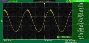
NFB disconnected. Now the output transformer doesn't make those sounds, but I can see the same waveform on the scope. Grid stoppers related? I'm gonna try and report.
Here is something to consider... If you have a high frequency oscillation you will not see it on the scope until you turn the sweep frequency up. I would step through each setting and see if you have other frequencies present.
NFB disconnected. Now the output transformer doesn't make those sounds, but I can see the same waveform on the scope. Grid stoppers related? I'm gonna try and report.
IMHO this looks like instability caused by transformer capacitance and somewhat suboptimal sectioning of primary winding.
Here is what to do next (all with NFB off).
1) Short the input.
2) Next, you need to isolate oscillating circuit. Try to take waveform with oscilloscope from the grids (connected to 2.2 uF MKP caps / 180k grid leak resistors) of output tubes. Most likely you will see around 1 mV of noise, but this is normal.
3) If output stage is oscillating (and most likely it is), in UL mode - connect RC network in series, 1.5K ... 4.7K 2W resistor + 470pF ... 2200pF capacitor, between anode and grid2 of each KT88. Try to use smaller resistor value and larger cap. If the oscillation stops, it means problem relates to transformer design. Try to feed amplifier with (8 Ohm dummy load connected) 20Hz, 2KHz, and 15KHz signal at different levels, and look what is happening on oscilloscope. Washed out waveform means oscillation.
4) Remove RC network, and switch output stage from UL to penthode or triode mode. If there is no oscillation, section arrangement in transformer is not optimized for UL, better to use it in triode or penthode mode only.
5) BTW - 40% UL is not so good for KT88, better to use 32% - 33%.
Last edited:
- Status
- This old topic is closed. If you want to reopen this topic, contact a moderator using the "Report Post" button.
- Home
- Amplifiers
- Tubes / Valves
- Problem with push-pull KT88