switches and binning 'matched' resistors
Some of the best advice here, actually. Potentiometers that carry significant long term DC current are always 'suspect' for future wiper (center contact) scratchy failure. Always. But in the short term, they are delightfully useful devices, as you have surmised.
One amplifier I made using LTP inverter, I also installed a DPDT switch: 'up', it engaged the potentiometer, just as you advised. 'down', and it pulled in a pair of resistors that matched the 'sweet spot', the last time the potentiometer was adjusted, and its particular value captured later via ohmmeter.
That way, no potentiometer long-term DC. Worked out really well.
Strictly speaking, you can also do this with an SPDT switch. One “one side”, use a fixed 4.7 kΩ resistor. On the other, the 0-to–10 kΩ pot. You still adjust the pot to find the sweep spot, but only “the other side” has its soldered-in resistor changed to match the findings. Less work.
Lastly, I think that 'listening for the sweet spot' is OK, but not great. Better is to use a 2 channel oscilloscope, employing its "A + B" summing mode. Since the outputs ideally are equal and symmetrical, as you vary the pot, you can easily see the best adjustment to minimize the difference signal. Easy, quick. Then, turn off amp and measure the pot's resistance. Then sift through one's resistor box to find a very-close match, or perhaps a couple of them in series to even more closely match the finding.
Anyway, as I frequently say, “I'm old, and I never buy 1% resistors”. However, having a LOT of them in vintages from 2020 back to 1960, allows me to poke around and find whatever value I need. Its not like my bench is a “production shop”. Poking around and testing a whole bunch of resistors while sipping beer watching a football game, with the 4½ digit DVM and a cardboard egg carton (to 'bin' the various values into) is truly one of life's easier tasks. Just watch the beer consumption! Binning gets error-prone after 3 cans.
LOL
⋅-=≡ GoatGuy ✓ ≡=-⋅
You can use a 5 kΩ or 10 kΩ potentiometer (1 Watt), connect the outer leads to the anode resistors and the center connector to the B+ for this stage. You can then look for a sweetspot, using a spectral display to see how harmonics (2nd, 3rd, etc.) increase and decrease. And of course don’t for get to listen with your ears!
Regards, Gerrit
Some of the best advice here, actually. Potentiometers that carry significant long term DC current are always 'suspect' for future wiper (center contact) scratchy failure. Always. But in the short term, they are delightfully useful devices, as you have surmised.
One amplifier I made using LTP inverter, I also installed a DPDT switch: 'up', it engaged the potentiometer, just as you advised. 'down', and it pulled in a pair of resistors that matched the 'sweet spot', the last time the potentiometer was adjusted, and its particular value captured later via ohmmeter.
That way, no potentiometer long-term DC. Worked out really well.
Strictly speaking, you can also do this with an SPDT switch. One “one side”, use a fixed 4.7 kΩ resistor. On the other, the 0-to–10 kΩ pot. You still adjust the pot to find the sweep spot, but only “the other side” has its soldered-in resistor changed to match the findings. Less work.
Lastly, I think that 'listening for the sweet spot' is OK, but not great. Better is to use a 2 channel oscilloscope, employing its "A + B" summing mode. Since the outputs ideally are equal and symmetrical, as you vary the pot, you can easily see the best adjustment to minimize the difference signal. Easy, quick. Then, turn off amp and measure the pot's resistance. Then sift through one's resistor box to find a very-close match, or perhaps a couple of them in series to even more closely match the finding.
Anyway, as I frequently say, “I'm old, and I never buy 1% resistors”. However, having a LOT of them in vintages from 2020 back to 1960, allows me to poke around and find whatever value I need. Its not like my bench is a “production shop”. Poking around and testing a whole bunch of resistors while sipping beer watching a football game, with the 4½ digit DVM and a cardboard egg carton (to 'bin' the various values into) is truly one of life's easier tasks. Just watch the beer consumption! Binning gets error-prone after 3 cans.
LOL
⋅-=≡ GoatGuy ✓ ≡=-⋅
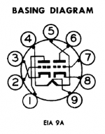
Looks like section 1 (pins 6,7,8) is not conducting current/conducting very little. Are both heaters lighting up? If not you may have a wiring mistake.So, can you solved? I have the same problem with a 12ax7
My B+ is 290v
Pin 6 = 288v
Pin 8,3 = 55v
Pin 1 = 170v
Mabe by the tube is bad?
For:
6.3V pins 4,5 connected together and pin 9.
12.6V pin 4 and pin 5. Leave pin 9 unconnected.
Or you may indeed have a bad tube (one of the heater sections is blown). Always check the simplest things first.
 Some discussion split to here -