Very simple....
With XLR connectors short 3 to 1 in other words the inverted signal known as cold to the shield or ground. This will unbalance a balanced connection.
If dealing with a terminal strip make a short jumper to go from ground/shield to the minus or cold.
I suggest that attention be paid to proper grounding. As stated prior...there needs to be only ONE ground for the system otherwise the nasty gtound loop monster comes out to play.
There a a number of us with pro audio experience under our belts and I can say that we have all dealt with the noise issues have provided the solution based on experience and textbook knowledge.
Banned
Joined 2002
I believe that BlackCatSound is pointing out that it is sometimes necessary to float the shield on one end of the equipment to eliminate the hum.CARTRulz, disconnect the wire from pin 1 on the XLR end.
This practice will and does vary from consultant to consultant. Some favor lifting the shield on the input and some on the output.

burnedfingers said:
This practice will and does vary from consultant to consultant. Some favor lifting the shield on the input and some on the output.
Makes no difference which end really, as long as you break the earth loop.
But it's very hard to diagnose and give a complete answer on a forum, I'm sure most of us here could cure it in a couple of minutes if we were there?.
But it's very hard to diagnose and give a complete answer on a forum, I'm sure most of us here could cure it in a couple of minutes if we were there?.
We have done it so many times that we don't give it a second thought anymore.
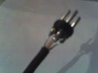
well the part that I dont understand is that these cables are low noise RCA to XLR cables, so haven't they already done what I would have to do anyway? Like I said before, On the RCA side there is one shielded wire that connects to the pin, and then another 2 that connect to the sleve, and then on the XLR side the shielded wire goes into pin 3 and the other 2 wires go into 1 and 2 respectively. So I left the shielded one alone becasue thats the signal wire, and since the other 2 were soldered to the sleve on the RCA side, I tied those together and soldered them to pin 1 on the XLR side, and ran a jumper wire between 1 and 2. I thought this was how its done, however I guess not becasue the hum is even worse. Is there a different procedure for using male and female XLR's? Becasue since its a equalizer its got 2 male inputs from the amp and then 2 female outputs back to the amp. So I guess its going from RCA to XLR with the males and from XLR to RCA for the females.
Thanks again for having the patience to work with me guys, you don't know how much I appreciate it.
Thanks again for having the patience to work with me guys, you don't know how much I appreciate it.
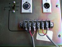
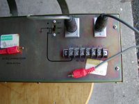
Here are 2 EXTREMELY low quality pictures, if you can discern anything from them I'll be surprised, but heres the deal. On the RCa side, the signal wire is the shielded one, and then theres that piece of flat metal which has 2 wires soldered to it at the bottom. Then on the XLR side theres the same signal wire, and the other 2 thinner wires go to pins 1 and 2. Isnt this procedure essentially the same exact thing as running the signal wire from one pin to another, and then running the shield to another pin and then having a jumper between them? Either way the signal wire takes one pin and the shield take the other 2, they just made it look nicer.
Attachments

This was scanned from a typical amplifier manual. In this case its an Altec Lansing model 9442. Its a commercial piece. Don't pay any attention to the voltage wiring chart at the top.
Figure #2
This is standard wiring practice for unbalanced and balanced in's and outs.
It clearly shows an unbalanced source going to the 9442 input and how to wire it.
Figure #2
This is standard wiring practice for unbalanced and balanced in's and outs.
It clearly shows an unbalanced source going to the 9442 input and how to wire it.
- Status
- This old topic is closed. If you want to reopen this topic, contact a moderator using the "Report Post" button.
- Home
- Loudspeakers
- Subwoofers
- Pro Audio Equipment In the Home