And a simple current limiting resistor/Thermistor can ignore all these niceties.
I think the relay is worthwhile . I suspect that's understood ?
Some of the ground covered here is very valuable to me . The idea that more than one waveform period is important will help me with a project I am designing .
http://www.hhvs.tnc.edu.tw/Departme...r paper was issued in IEE prdceedings-EPA.pdf
Very much so.I think the relay is worthwhile . I suspect that's understood ?
The current limiting resistor is there for start up only.
After that the amplifier requires that the PSU sees a low source impedance. If not, then the PSU cannot recharge properly.
Just catching up with the posts. Hopefully this helps.
Too much emphasis on DCR of the windings.
Flux in the core is equal to the integral of the voltage applied. If the xfmr is energized at voltage zero-crossing, the flux will be fully offset from zero (hence the failed attempt to point out assymetrical vs. symmetrical analysis). The peak value for a fully offset sine wave is twice normal, so the flux is twice that encountered in steady state. This offset flux with high magnitude drives the core into saturation (only only the positive or negative going peak).
When the core is in saturation, inrush current is limited by the complex impedance consisting of the air core impedance of the winding and its DCR. For a toroid this complex impedance may approach the DCR, but too much simplification leads to errors in understanding.
The condition can be even worse when the core has residual flux from its prior de-energizing, but you have to get lucky. The direction of the residual flux has to be in the same direction as the energizing flux.
If you had theoretically zero resistance, inrush would continue forever. The real world assymetry decays approximately by the L/R time constant. Large power transformers can take many seconds for inrush current to decay.
It is safe to approximate that inrush current of a transformer is equal to the short circuit current of the same transformer.
Hi everybody. I have been out due to my computer keep crashing finally found the problem in the video board. Found 5 capacitors sponged and leaking the electrolyte. replaced them and it is running OKAY again
nigel I read your document very good. That means my design it is using option 3 by controlling the firing angle of the wave cycle.
Tried it in my FM tube tuner and no bright filament when switching it ON. It is was smooth in the turn on.
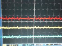
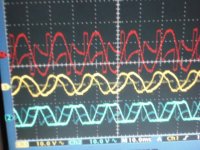
Also I have new better pictures of the toroid secondary output voltages. the last one I forget to zero the 2 input probes and didn't looked to good.
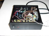
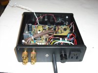
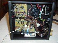
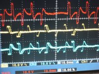
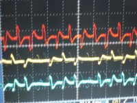
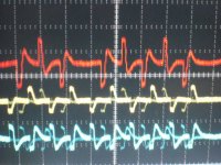
Also I implement the zero crossing to my stand alone speaker protection to switch ON/OFF the amplifier plus monitor the current output to the speakers. If the current it is too high it will open the speaker SSR and shutdown the amplifier.
Attached are the picture for the voltage waves signal when switching ON/OFF the toroidal transformer.
nigel I read your document very good. That means my design it is using option 3 by controlling the firing angle of the wave cycle.
Tried it in my FM tube tuner and no bright filament when switching it ON. It is was smooth in the turn on.
Also I have new better pictures of the toroid secondary output voltages. the last one I forget to zero the 2 input probes and didn't looked to good.
Also I implement the zero crossing to my stand alone speaker protection to switch ON/OFF the amplifier plus monitor the current output to the speakers. If the current it is too high it will open the speaker SSR and shutdown the amplifier.
Attached are the picture for the voltage waves signal when switching ON/OFF the toroidal transformer.
Attachments
-
 AC 1.JPG214.6 KB · Views: 203
 -
 Speaker protect stand alone 3.JPG215.3 KB · Views: 63
 -
 Speaker protect stand alone 2.JPG213.5 KB · Views: 61
 -
 Speaker protect stand alone 1.JPG212.8 KB · Views: 74
 -
 AC5.JPG211 KB · Views: 185
 -
 AC4.JPG211.1 KB · Views: 200
 -
 AC3.JPG213.1 KB · Views: 196
 -
 AC2.JPG213 KB · Views: 195
maximum possible inrush current happens when the primary of the transformer is turned on at the peak of the wave cycle, and it is Vpk/Rdcr, where Vpk is the peak of the ac input voltage and Rdcr is the dc resistance of the transformer primary, i can not imagine getting higher currents than this....
it is this current that needs to be tamed by adding resistance in series to lower this current.....can not be simpler than this....
it is this current that needs to be tamed by adding resistance in series to lower this current.....can not be simpler than this....
was it Eva in the singing toroid/DC blocking discussion?
mlloyd1
mlloyd1
...snip...
I recall a year or so back another Member did some current peak tests or simulations and found the instantaneous peak was >50% of the primary resistances estimate. I can't remember the name, nor the method, nor the numbers.
maximum possible inrush current happens when the primary of the transformer is turned on at the peak of the wave cycle,....
No, worst case is (approximately) when the transformer is turned on at the zero crossing (of the voltage waveform).
The current peak will occur between 90° to 180° later, depending on the design margins of the transformer.
If they are absolutely minimal, the peak will occur near 90°, the voltage peak, and it will be maximum in amplitude and last longer.
can someone show experimental results to confirm, or otherwise, this myth?No, worst case is (approximately) when the transformer is turned on at the zero crossing (of the voltage waveform).
The current peak will occur between 90° to 180° later, depending on the design margins of the transformer.
If they are absolutely minimal, the peak will occur near 90°, the voltage peak, and it will be maximum in amplitude and last longer.
can someone show experimental results to confirm, or otherwise, this myth?
Me too Andrew . This is important .
It appeals to me to say 2.5 mS is significant if 50Hz . The rest I have no idea about .
One should speculate about class B and D amplifiers if so . The transformer will inter-modulated and include the 50 or 60 Hz time constant . Naim perhaps discovered a truth ? I would further speculate that a well designed class B might have unimagined advantages over class A if so ? The transformer using it's saturation qualities better ? I am not gifted in the maths of this so happy to be very wrong . The Carver idea seems a logical extension of this .
If we put on one side the inrush current caused by a cap input PSU hanging off the secondary, then the 'zero crossing is worst' claim is not a myth. It is a fact, which can be easily shown to anyone who understands integral calculus and circuit theory. I gave a link in an earlier post. For a lightly loaded transformer switched on at the voltage peak there will be no DC current in the primary and so probably no saturation.
Switching on at the voltage zero crossing gives a DC current equal to the peak AC current, so the peak is doubled which will almost certainly cause saturation and an even bigger current pulse.
A large inrush current from the secondary could also cause a large primary current simply via normal transformer action. However, this might not cause saturation as the secondary current balances the primary current.
Dispelling that myth may require some serious disconnection of the reality. Substances may help.can someone show experimental results to confirm, or otherwise, this myth?
http://lmgtfy.com/?q=inrush+current+transformer+core+saturation&l=1
Leading to this for example:
Transformer Inrush Current
I think telling Andrew to use inrush thermistors is a bit wrong as he advocated them ( yes I did see the text ) . What is a more interesting question is do they allow more useful transformer design ? Also if given the choice what is the better switching point to use when energizing a transformer ? It might be V peak .
ftp://kavcrl.dyndns.org/+MEDIA/+ELE...ltage Switching Resonant Power Conversion.pdf
ftp://kavcrl.dyndns.org/+MEDIA/+ELE...ltage Switching Resonant Power Conversion.pdf
I am pretty sure you know that we are not talking about the secondary charging of the capacitor input filter.If we put on one side the inrush current caused by a cap input PSU hanging off the secondary, then the 'zero crossing is worst' claim is not a myth
I am also pretty sure you also know that we are talking about the start up current that the transformer tries to draw from the mains before the secondary has even started to charge up that capacitor input filter.
Stop trying to confuse two different issues.
I am certainly NOT referring to slow charging of the capacitors.
I am talking about the start up current of the transformer.
Now show us the truth of the myth. Show us the experimental data that confirms that the transformer primary draws an inductive loaded type current, that is zero when the instant of switch on coincides with the peak of the voltage waveform.
I asked anyone for the evidence earlier, now I challenge you!
I was carefully separating the two issues, just in case others tried to confuse them!AndrewT said:Stop trying to confuse two different issues.
I have no experimental data. I just use a bit of calculus and knowledge of how an inductor behaves when a voltage is applied across it. You can do the same. This is standard texbook stuff. You can also find it on several websites if you don't have the appropriate textbooks to hand. Some links have already been given in this thread.
"inrush current caused by a cap input PSU" is equal to including the cap as part of the load. I am excluding the cap as a load. Disconnect it or remove it or add a big resistor into the secondary circuit and then look at the start up condition for the primary side.If we put on one side the inrush current caused by a cap input PSU hanging off the secondary, then the 'zero crossing is worst' claim is not a myth.
Now compare the two start up conditions.
One where the voltage waveform is at zero crossing and the switch is closed.
The second is where the voltage waveform is at peak and the switch is closed.
The "myth" claims that for the first case (zero crossing) the instantaneous start up current is at worst case maximum and in the second case (at Vpeak) the instantaneous start up current is zero because transformer behaves as an inductor.
The Wiki link does show the current pulse. But unfortunately does not show the phase of the voltage waveform.
Experimental data showing the voltage waveform and the current during the start up phase, show whether the inductance is dominant or the resistance is dominant, during the start up. Or maybe somewhere in between. Let's see the data.
Now, add on a capacitive load to the secondary and the results will be different. I accept they will look different. But that is not the discussion here.
Last edited:
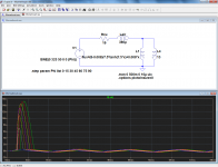
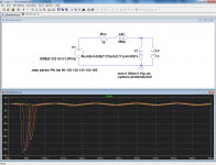
Here is a simulation for a typical, minimally designed 230V 100VA toroidal transformer (unloaded).
First, the starting angle of the voltage waveform is varied from 0° (green trace) to 90° (blue trace).
Next, the starting angles are varied from 90° (green) to 165° (gray)
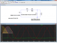
And finally, the explanation with the two extremes:
The core sees the area subtended by the red sinewave. When the waveform starts at 90°, it only sees the yellow area, and then it reverses.
But when the waveform starts at 0°, it has to endure the whole pink area before being allowed to "breathe": it saturates quickly after 90°.
First, the starting angle of the voltage waveform is varied from 0° (green trace) to 90° (blue trace).
Next, the starting angles are varied from 90° (green) to 165° (gray)
And finally, the explanation with the two extremes:
The core sees the area subtended by the red sinewave. When the waveform starts at 90°, it only sees the yellow area, and then it reverses.
But when the waveform starts at 0°, it has to endure the whole pink area before being allowed to "breathe": it saturates quickly after 90°.
Attachments
- Status
- This old topic is closed. If you want to reopen this topic, contact a moderator using the "Report Post" button.
- Home
- Amplifiers
- Power Supplies
- Preventing the inrush current saturation in a toroidal/EI transformer