I wonder what good the shelving lowpass does, except make the woofer go lower, except the woofer already goes very low due to positive feedback at low frequencies.
This so-called shelving lowpass is actually the approximation of a PI controller if it is placed in the forward path of the loop.
To see what Elektor did with the piezo acceleration sensor example I would have to undig the article (I remember that I have it somewhere).
Regards
Charles
>@bwaslo: could you sketch your filter topology, please?
Sorry to take so long getting this on the board, I was out of town and didn't have any files with me (other than a few plots on my laptop).
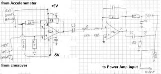
Here is a sketch of the topology (sorry for the crummy drawing). I took the parts values off, as I don't know how AudioXpress would feel about me giving out the design before they publish it. But you can see what is happening from the topology, I think. Notice that the ACH-01 accelerometer output is inverted, so its signal gets fed back in-phase (to the inverting input of the summing stage, and then inverted again by the leaky integrator stage). R8A gives an adjustment for the loop gain. R9, 10, 11 and C5,6,7 make up the Twin-T notch (and when loaded by R12, there is a relative high frequency boost from the notch, which gives a phase lead). You can calculate the Twin-T notch frequency to take out any peaks in your loop, using the formula at
www.radio-electronics.com/info/circuits/rc_notch_filter/twin_t_notch_filter.php
Sorry to take so long getting this on the board, I was out of town and didn't have any files with me (other than a few plots on my laptop).
Here is a sketch of the topology (sorry for the crummy drawing). I took the parts values off, as I don't know how AudioXpress would feel about me giving out the design before they publish it. But you can see what is happening from the topology, I think. Notice that the ACH-01 accelerometer output is inverted, so its signal gets fed back in-phase (to the inverting input of the summing stage, and then inverted again by the leaky integrator stage). R8A gives an adjustment for the loop gain. R9, 10, 11 and C5,6,7 make up the Twin-T notch (and when loaded by R12, there is a relative high frequency boost from the notch, which gives a phase lead). You can calculate the Twin-T notch frequency to take out any peaks in your loop, using the formula at
www.radio-electronics.com/info/circuits/rc_notch_filter/twin_t_notch_filter.php
Attachments
>Bwaslo how much feedback can you achieve without oscillation?
For the article design, I'm using about 10dB feedback (at ~70Hz, the highest point in the "raw" response), leaving 8dB or more of gain margin over the full range. The feedback is at about 0dB at 20Hz, and phase shift is what kicks the response up below that frequency, from slight peaking. I could use more feedback, but the peaking starts to look ugly and scary if taken too far, and I wanted to keep it moderate for the article.
I've done another in which I had stiffened the cone and dust cap with a coat of epoxy (to move the resonance to above 1200Hz) and was able to use about 15dB of feedback, without visible peaking, with that one. But that approach will only work if you can measure the resonance and custom tune the notch for it, since I doubt the resonance shift would be very repeatable from smearing some uncontrolled thickness of epoxy on the cone.
BTW, I just yesterday found out that the distortion graph I uploaded previously is wrong -- I forgot about low frequency resolution limits and didn't use a long enough measurement for the plot to be correct below about 30HZ. It will probably look better than I showed at lower frequencies (though I guess it could instead be worse than shown... the FFT size wasn't long enough to show anything valid about the very low frequencies). I'll remeasure and post the correct distortion measurement after I get back home again and have some time.
Redone distortion plots, at long last
I finally got a chance to rerun the distortion measurements on the servo-d Sub120. This is the design that will be published in AudioXpress.
I set the sub up in my listening room, about 1 meter from a wall and with the microphone 2 meters away, a meter from the floor and toward the center of the room. That's a pretty typical listening distance for small rooms. Then made measurements at various drive levels.
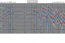
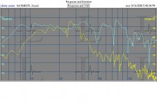
Here is the series of fundamental sweeps, to show how the output compresses. You can see the room lift along with the usual modes and nulls. The design has a highpass filter at about 16Hz, but the response is still strong below that in this case because of the room. The input drive at lower frequencies is rolling off fast, so you can see that the compression lets up below about 10Hz -- the output there is mostly being peaked by the room. Which would be advantageous if I had any CDs with actual content that low!
I finally got a chance to rerun the distortion measurements on the servo-d Sub120. This is the design that will be published in AudioXpress.
I set the sub up in my listening room, about 1 meter from a wall and with the microphone 2 meters away, a meter from the floor and toward the center of the room. That's a pretty typical listening distance for small rooms. Then made measurements at various drive levels.
Here is the series of fundamental sweeps, to show how the output compresses. You can see the room lift along with the usual modes and nulls. The design has a highpass filter at about 16Hz, but the response is still strong below that in this case because of the room. The input drive at lower frequencies is rolling off fast, so you can see that the compression lets up below about 10Hz -- the output there is mostly being peaked by the room. Which would be advantageous if I had any CDs with actual content that low!
Attachments
Servo'd Sub120 Distortion Plots, cont'd
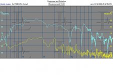
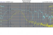
Here is the fundamental (top trace) and summed harmonic distortion components (lower trace) for the highest level sweep at which the woofer still was moving linearly at all frequencies.
This shows the difference in levels between fundamental (only) and all distortion components below 12th order. The measurement method (log-swept sine) is able to measure fundamental level by itself.
To get to %THD, if you need those values, take the difference between the fundamental and the distortions at any frequency and level, call it "D", (a positive value in dB). From that calculate the fractional equivalent "E", as : 10^(-dB/20). Then the percent distortion is
%distortion = 100*E/(1+E).
Attachments
I just discovered a bit of a problem with my microphone setup, I noticed the amp was clipping at not so high levels, so I watched with the scope and noticed that it was only clipping on the negative rail.
It turned out the micrphone was clipping on the negative side of the wave, which caused the feedback circuit to boost the signal, causing the amp to clip.
I guess it's not normal for a microphone to deliver a signal of 500 mV.
I'm thinking about placing the microphone about 5 cm away from the woofer, the spl should be alot lower, also room modes are better equalized.
Servo Feedback Kit
I wish Rod Elliot or BrianGT or someone else known for their electronics kits would come out with a servo feedback project with an accelerometer we could just glue onto the back of any speaker cone, and with controls that we could adjust for our specific driver and design. It would have a mono line-level input and a line-level output which enters into the amplifier. With that level of ease, any project could be servo-controlled. The servo-correction signal would need an adjustable low-pass filter and an adjustable high-pass filter. These functions could be accomplished by small PCB-mounted pots, with set-and-forget simplicity.
I wish Rod Elliot or BrianGT or someone else known for their electronics kits would come out with a servo feedback project with an accelerometer we could just glue onto the back of any speaker cone, and with controls that we could adjust for our specific driver and design. It would have a mono line-level input and a line-level output which enters into the amplifier. With that level of ease, any project could be servo-controlled. The servo-correction signal would need an adjustable low-pass filter and an adjustable high-pass filter. These functions could be accomplished by small PCB-mounted pots, with set-and-forget simplicity.
Such a circuit would be quite hard to tune without an oscilloscope, also people with a scope are in general able to build such a circuit themselves.
It only works when a certain woofer is supplied, like the kit from rythmik audio.
I would like so see someone like Rod Elliot to post an article on subwoofer feedback though.
It only works when a certain woofer is supplied, like the kit from rythmik audio.
I would like so see someone like Rod Elliot to post an article on subwoofer feedback though.
The Rhythmik woofer doesn't incorporate an accelerometer, but uses a specially-wound second coil to sense the voice coil's position within the magnetic gap. This would be a kit that includes the accelerometer and the associated circuit. The accelerometer would simply be adhered to the cone of the woofer and connected with flexible multi-stranded leads, not built into the driver. Something would need to be done to compensate for the shorter excursions of smaller drivers, but this could be incorporated into the adjustments that the user would make. And that adjustment might require an oscilloscope, but I don't see where the assumption comes from that everyone who owns an oscilloscope will be an electrical engineer who can develop their own circuit anyway. It would be much simpler to order the kit from Elliot Sound Products and tune it to match the woofer being used, than to design a circuit from the ground up.
I really like the notion of usong a mic for feedback. It will both work for lowering the distortion in the sub, correcting Q and freq response, at the same time working as active room correction.
In fact this is more or less "just" an active bass absorber, that has an extra input for producing bass sound")
bobo1on1: how does it sound?
In fact this is more or less "just" an active bass absorber, that has an extra input for producing bass sound
bobo1on1: how does it sound?
Imagine having a woofer made from concrete, not just the case, but the cone as well.
It sounded incredibly tight, I had to turn up the volume around 5 db because it sounded less loud, even though the measuring equipment said it was at the same volume.
I did have a problem with the microphone clipping one way, at first I thought it was the amp but when I checked it with the scope the amp was only clipping to the bottom rail.
Hi Baldin
---I really like the notion of usong a mic for feedback. It will both work for lowering the distortion in the sub, correcting Q and freq response---
A mike would do about the same job as an accelerometer.
It is very little known what are the subtle effects of the different kinds of motion feedback. As far as I could determine them :
Acceleration feedback alone makes the moving mass apparently higher, so the frequency resonance is lower. The then higher Qt has to be corrected through the associated electronics.
Velocity feedback alone only lowers the Qt making the driver having an ascending frequency response at a rate of 6 dB/o. The associated electronics can differentiate the feedback signal, making it an acceleration information (as used by Dan Ferguson in its AudioXpress articles ) or it can integrate the input signal (as used by Russell Breden in its Electronics World article) to get extension of the low frequency response.
Position feedback alone enhances the stiffness of the suspension, then the frequency resonance and the Qt are enhanced.
- Status
- This old topic is closed. If you want to reopen this topic, contact a moderator using the "Report Post" button.
- Home
- Loudspeakers
- Subwoofers
- Pressure based motional feedback.