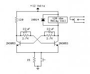
Hello all, so I needed a simple transistor based toggle/flip flop circuit to turn a momentary spst switch into a latching type. This circuit looks ok, but my question is will this circuit power up in the same state every time? If not, is there a way to modify it to do so? Thanks!
Attachments
Hi,
I don't see how this can toggle? Toggling normally involves saturating one half by for insyance pulsing its base so that the other side comes out of conduction, and vice versa. What you do here is momentary increasing the current in both halves. Tghe pushbutton should be between supply and one of the bases (with a series R of course).
The defined switch-on is normally done with something like a cap from supply to one base to delay that half so the other half switches on first.
Jan Didden
imix500 wrote:
Is this what ur looking for ?circuit to turn a momentary spst switch into a latching type
Attachments
Thanks guys. I was wondering about it charging both sides myself. The explanation provided with the circuit said that one capacitor will charge slightly faster than the other and switch first. Not sure if this is right though. Wouldn't be the first time I pulled a bad circuit off the web.
gmphadte, that looks more like what it should be. Any idea if it will power up with one side on every time?
cpemma, neat idea of using a mosfet. Will it toggle on/off?
Thanks!
gmphadte, that looks more like what it should be. Any idea if it will power up with one side on every time?
cpemma, neat idea of using a mosfet. Will it toggle on/off?
Thanks!
The first curcuit posted will function quite well as a T-Latch (Toggle Latch).
I use it in a lot of my work because of its inherent simplicity.
If you get the values too out of place, it will become an astable multivibrator, which you don't want.
Either way, the circuit does work as stated.
If you want to get it to start in one state all the time, you have to add a little imbalance to it so that it will 'lean' over to that state a bit, but not enough to get stuck there.
Hi Duo, that's good news since I already ordered parts to make up a few to try. I figured I would use the values as is with the only difference being that I'm using 2n2222 instead of the 2n3053.
So, how should one side be "biased" to come on first? Just increase one 2.7k to a higher value?
So, how should one side be "biased" to come on first? Just increase one 2.7k to a higher value?
imix500 said:cpemma, neat idea of using a mosfet. Will it toggle on/off?
Thanks!
Works in simulation, I'm waiting for a small mosfet to try it, 2N7000 also should be OK.
The problem with all toggles is catering for switch bounce, your first circuit may be sensitive.
A couple more circuits here.
Hi cpemma, those look like great designs. One constraint is that I will have to build 24 of these to accomadate 24 switches. Simpler is better both in time to build and space needed. However, if debouncing is going to be a problem I will have to go with a more complicated design. I will raid the parts bin and see if i can build your circuit.
Thanks!
Thanks!
If you're going to make 24 of them, I would suggest getting some logic chips to do it for you.
Use SR latches as debouncers and then JK FFs to make the toggles. This way you could achieve a great space, power, cost, time, and design savings.
You can get the 74LS276 which is a quad JK flip-flop with indvidual clock inputs. You simply tie J and K active and then toggle the clock input to make it toggle.
With the '276, it's very easy to make it start in one state because there's a reset pin. You just make a pulse generator out of cap and resistor to pulse that pin when power is applied, thus resetting the whole thing to all outputs low. If you want to set all high on power on, then leave the reset pin high and pulse the preset pin. Very versatile I think. This leaves you at 6 chips for the toggle FFs.
Then you use 74LS279 which is a quad SR latch for debouncing of switches if necessary. Thus bringing your total to 12 chips instead of a mess of transistors.
If you want a schematic, I could make one up.
Hope that helps.
imix500 wrote
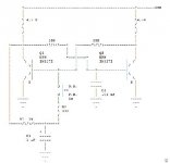
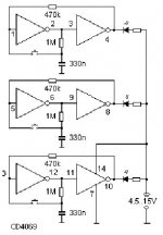
4027 is a dual JK FF
see the attached schem.
I don't know whether it starts in reset state always. If not all u have to do is use a power on resest ckt using CD4541 and connect it to these ckts using a driver to increase fanout, but by replacing a 2 input gate like CD4093. Power on reset can also be made using a scmidt gate and RC
Also I feel that a 4093 as the frontend; with RC, in the ckt attached should solve power on problem if exists. Then all above is not needed.
Gajanan Phadte
Yesgmphadte, that looks more like what it should be. Any idea if it will power up with one side on every time?
4027 is a dual JK FF
see the attached schem.
I don't know whether it starts in reset state always. If not all u have to do is use a power on resest ckt using CD4541 and connect it to these ckts using a driver to increase fanout, but by replacing a 2 input gate like CD4093. Power on reset can also be made using a scmidt gate and RC
Also I feel that a 4093 as the frontend; with RC, in the ckt attached should solve power on problem if exists. Then all above is not needed.
Gajanan Phadte
Attachments
")
gmphadte, so is the circuit you posted all I would need then?
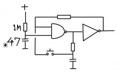
No. this circuit does not guarantee power on status.
Just change the left gate to a 2 input scmidt gate like 4093 and put an RC at the second input and u are done.
Gajanan Phadte
Attachments
- Status
- This old topic is closed. If you want to reopen this topic, contact a moderator using the "Report Post" button.
- Home
- Design & Build
- Parts
- Predict this Toggle Circuits behavior