Hi Gents,
Maybe y'all can point me in the right direction. I'm interested in improving
the quality of the ARC SP3A1 that I have and and researching adding a
DC servo for the power supply. 'Cept I'm more of a Tube guy and
I'm learning about Solid State.
So, any advice would be apprecitated. I'm in the R&D aspect of it now.
Cheers,
Sync
I'm interested in improving
the quality of the ARC SP3A1 that I have and and researching adding a
DC servo for the power supply.
How would you use a servo in a tube preamp, do you mean a regulator?
> adding a DC servo for the power supply.
It IS a DC servo.
At least in the manual I found.
If a sample of the output does not equal a reference voltage, the diff-pair shoves the pass-tube (OK, FET) to servo until equality happens.
It took a few moments to figure that out. But clearly someone worked many-many-many moments to develop it. I would not go hacking into it without massive experience.
Attachments
> adding a DC servo for the power supply. It IS a DC servo.
A servo has very narrow bandwidth, rolling off below the audio band starts.
In audio it's mostly used for nulling a DC voltage offset.
A good regulated power supply has wide bandwidth, hopefully wider than
the bandwidth of the input signal.
Last edited:
I'm interested in improving the quality of the ARC SP3A1
that I have and and researching adding a DC servo for the power supply.
Check into one of the various SP3 power supply regulators that have been done,
like the "Paoli mod".
@Rayma & @PRR
OH wow, thanks for the manual with the SP3C....
Let me repost what I found. I found a thread I thought would work.
Here is the Paoli Mod and it's patent: LINK
Funny thing though, I was 12 years late to the party. I've found the schematic
and the patent. Maybe it is just simpler for me to link to that old post I don't know if I can
move the contents over here.
Probably better to use the link above I can't seem to re-link these.
Cheers,
Sync
Attachments
Last edited:
@PRR
ON the servo it self, are those your notes in the image?
My pre amp power supply looks nothing like that (i think).
It's and upgraded original from ARC.
It's in service right now I'm in the R&D phase. Just trying to
think of things to upgrade.
Cheers,
sync
ON the servo it self, are those your notes in the image?
My pre amp power supply looks nothing like that (i think).
It's and upgraded original from ARC.
It's in service right now I'm in the R&D phase. Just trying to
think of things to upgrade.
Cheers,
sync
> adding a DC servo for the power supply.
It IS a DC servo.
At least in the manual I found.
If a sample of the output does not equal a reference voltage, the diff-pair shoves the pass-tube (OK, FET) to servo until equality happens.
It took a few moments to figure that out. But clearly someone worked many-many-many moments to develop it. I would not go hacking into it without massive experience.
Servo Loops. Gain, Reference, Feedback, Bandwidth, Overshoot, Damping, etc.
Very tricky.
Just for fun, here are some older servo loops you may never thought of that way:
Insulin loop (eat some sugar)
Heart rate (climb a hill)
Breathing rate (come up for air after 30 seconds underwater)
Eye tracking, muscle motion (watch and hit a baseball)
If any of them go open loop, you may have a problem.
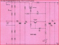
That Paoli thing stinks, the regulating amp is getting it's power with the ripple from the input.
If you want to keep it simple, a German design, don't put the resistors in the bridge (leftover from sim).
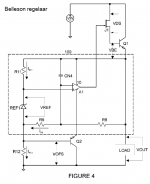
And Bellison had a great idea too.
Mona
If you want to keep it simple, a German design, don't put the resistors in the bridge (leftover from sim).
And Bellison had a great idea too.
Mona
Attachments
Last edited:
Zo Mona,
If I undserstand correctly:
Der maz Ausgangsstrom betraegt....
Remove the 4 x 6R8 resistors...also then where to the
320V max connections...to a center tap transformer or
what might the connection be?
Or were those used as a measurement point?
Thank you for the analysis. I didn't now the servo regulator
was fed the ripple current? I was thinking it was down stream
but I haven't studied the SP3C that PRR linked to on the very last
page is a mark up.
@6A3sUMMER, that was a good explanation about what a servo does.
It checks things out and adjusts for load...whether heart rate in runner,
insulin in blood or breathing rate or lack there of....Thanks.
Cheers,
Sync
Cheers,
Sync
That Paoli thing stinks, the regulating amp is getting it's power with the ripple from the input.
If you want to keep it simple, a German design, don't put the resistors in the bridge (leftover from sim).
And Bellison had a great idea too.
Mona
Last edited:
A sim prog wants to now the resistance of the current delivery source.Therefore you put them in the drawing.In practice the transformer has resistance of it's own, no need for external ones.Replace them by wires.Zo Mona,
If I undserstand correctly:
Der maz Ausgangsstrom betraegt....
Remove the 4 x 6R8 resistors...also then where to the
320V max connections...to a center tap transformer or
what might the connection be?
Or were those used as a measurement point?
As drawn the circuit is for a simple winding, if you have a center tap remove two diodes an connect the tap to ground.
Max current depends on the transformer , the voltage drop on the pass transistor (dissipation) and amount of cooling.
The patent paper shows a circuit with the controling opamp on a lower voltage derived from the input power not from the stabilised output voltage.Thank you for the analysis. I didn't now the servo regulator
was fed the ripple current? I was thinking it was down stream
Mona
- Status
- This old topic is closed. If you want to reopen this topic, contact a moderator using the "Report Post" button.
- Home
- Amplifiers
- Tubes / Valves
- Preamp Servo Filter