Greetings,
After getting this circuit from Eli (thank you!), I decided to try to roll a preamp design based on this circuit (see below).
I was hoping to get some feedback before I cut the PCB. My main concern is component selection since this impacts layout. More on that shortly.
First, here is a link to the system architecture.
http://www.mdbq.net/audio/sysblk01.pdf
The two power supply modules are simply linear regulated supplies made by International Power. They are cheaper than rolling my own when you consider the cost of making a PCB and sourcing a transformer.
The phono stage is TBD and is not considered in this review.
The FET line out is Eli's work and is described in another post about driving long lines.
The crux of the review is the line amp. Yes, I plan to have a tone circuit defeat switch, but the tone controls are a desired feature, too. The attenuation for the defeat path is to be determined.
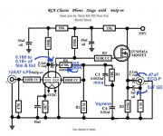
Here is the schematic:
http://www.mdbq.net/audio/LineAmpSchem01.pdf
The resistors are either 1/4 metal film or 2W metal film. The board layout has provisions for the 2W resistors where they might be needed.
The capacitors are a little more tricky. I normally order parts from Digikey for my business, so it is convenient to use them as a source. Here are the Digikey part numbers for the three caps:
C1 & C4 1800 pF 500 WVDC Mica 338-2871-ND
C2 & C3 10 µF @ 100 WVDC Polyester, Metallized Film 495-4099-ND
C5 & C6 47 µF @ 200 WVDC Electrolytic P5914-ND
DigiKey Electronics - Electronic Components Distributor
The filaments are tapped right at the sockets. Pins 4, 5, & 9 are brought out, but I plan on using only pins 4 & 5 powered by 12 VDC.
The board is a 4-layer board. One internal layer is used for ground. The second internal layer is not used.
I did not think using an internal layer for 250 VDC was wise. I am not sure what to do with this layer.
One thought is to delete it.
Another idea is to simply place a grounding via at only one corner of the board to this plane (so there is no ground loop), but it would create a capacitor,
What is the best thing to do?
The layout can be found at:
http://www.mdbq.net/audio/PCB01.jpg
Please let me know what you guys think and what is right or wrong. I appreciate your feedback and will be happy to answer any questions.
After getting this circuit from Eli (thank you!), I decided to try to roll a preamp design based on this circuit (see below).
I was hoping to get some feedback before I cut the PCB. My main concern is component selection since this impacts layout. More on that shortly.
First, here is a link to the system architecture.
http://www.mdbq.net/audio/sysblk01.pdf
The two power supply modules are simply linear regulated supplies made by International Power. They are cheaper than rolling my own when you consider the cost of making a PCB and sourcing a transformer.
The phono stage is TBD and is not considered in this review.
The FET line out is Eli's work and is described in another post about driving long lines.
The crux of the review is the line amp. Yes, I plan to have a tone circuit defeat switch, but the tone controls are a desired feature, too. The attenuation for the defeat path is to be determined.
Here is the schematic:
http://www.mdbq.net/audio/LineAmpSchem01.pdf
The resistors are either 1/4 metal film or 2W metal film. The board layout has provisions for the 2W resistors where they might be needed.
The capacitors are a little more tricky. I normally order parts from Digikey for my business, so it is convenient to use them as a source. Here are the Digikey part numbers for the three caps:
C1 & C4 1800 pF 500 WVDC Mica 338-2871-ND
C2 & C3 10 µF @ 100 WVDC Polyester, Metallized Film 495-4099-ND
C5 & C6 47 µF @ 200 WVDC Electrolytic P5914-ND
DigiKey Electronics - Electronic Components Distributor
The filaments are tapped right at the sockets. Pins 4, 5, & 9 are brought out, but I plan on using only pins 4 & 5 powered by 12 VDC.
The board is a 4-layer board. One internal layer is used for ground. The second internal layer is not used.
I did not think using an internal layer for 250 VDC was wise. I am not sure what to do with this layer.
One thought is to delete it.
Another idea is to simply place a grounding via at only one corner of the board to this plane (so there is no ground loop), but it would create a capacitor,
What is the best thing to do?
The layout can be found at:
http://www.mdbq.net/audio/PCB01.jpg
Please let me know what you guys think and what is right or wrong. I appreciate your feedback and will be happy to answer any questions.
In my opinion:
1) the switch to bypass the tone stage is useless.
2) Use of a electrolytic capacitor of too large voltage rating is also useless, it is said that a capacitor of, say, 100V WV used with a voltage of 16V never will be formed as it must, and the results is a lower final cap. I don't know if it is true or not.
Lots of luck in the project!.
Regards,
Osvaldo.
In my opinion:
1) the switch to bypass the tone stage is useless.
2) Use of a electrolytic capacitor of too large voltage rating is also useless, it is said that a capacitor of, say, 100V WV used with a voltage of 16V never will be formed as it must, and the results is a lower final cap. I don't know if it is true or not.
Lots of luck in the project!.
Regards,
Osvaldo.
Thanks for the reply. What voltage should the cap be rated for?
C5,C6, try for 10V, 6.3 if you can find it.
Okay:
Digikey # 493-4636-1-ND
UKA1A470MDD1TD Nichicon | 493-4636-1-ND | DigiKey
A WV immediately upper than the expected in the circuit. Example, in a 12V circuit, it is of no sense to use 200V cap's, use, 16 or almost 25V. You will save cost, space, and hours of life of them.
I don't know about cap manufacturers for audio, and their reputation and how them "sound". Positively I can affirm that Nichicon are one of the bests for switching power supplies. Lots of experience in this job.
I don't know about cap manufacturers for audio, and their reputation and how them "sound". Positively I can affirm that Nichicon are one of the bests for switching power supplies. Lots of experience in this job.
Last edited:
I'd scrap the tone control. If you want to correct for room acoustics or recording imperfections, I suggest using a graphic EQ instead.
I'd just go with the right part of the circuit. So from W5 and on.
It's not clear from your layout, but it looks like you're planning to use a ground plane. I recommend against that. You have better control over the ground currents if you use a star ground topology. I also don't like ground planes in high-voltage circuits as the clearance requirements between HV connections and the ground planes make the ground plane really spotty and rather useless.
You'll need grid leak resistors to ground and a volume control somewhere. Grid stoppers would be handy as well.
If I interpret your schematic correctly, the line stage and output stage are a grounded cathode amp followed by a cathode follower. The LF pole on the cathode follower is set by C1, R7. 1.8 nF, 1 Mohm makes a pole at 90 Hz. So your amp will cut off most of the LF. I suggest increasing C1, C4 to at least 22 nF. Higher if you want to avoid excessive phase change in the lower octaves of the audible frequency range.
~Tom
Last edited:
1st and foremost, you switch the entire tone control block, not just the signal shaping elements, into or out of the signal path.
Max Robinson's overall "unity gain" Baxendal implementation is merely the point of departure. Remember, I said 4 bottles just for tone controls is too much. Replace the cap. coupled cathode followers with DC coupled ZVN0545A source followers and you halve the bottle count. You also reduce the number of caps. in the signal path, which is "always" a good thing. The tweaked RCA phono preamp schematic I've uploaded shows how to implement DC coupled ZVN0545A source followers.
Please no polyester film in the signal path. "Teflon", polystyrene, and polypropylene constitutes the sonic transparency pecking order. For several practical reasons, polypropylene film is (IMO) usually the "best" choice. C1 and C4 disappear, when DC coupling is employed. Use Nichicon KZ series 'lytics for C5 and C6.
The value of O/P coupling caps., like C2 and C3, is controlled by the I/P impedance of the downstream circuitry. The coupling cap./I/P impedance combo form a high pass pole. Most of the time, F3 of that pole should be no greater than 5 Hz. Metalized polypropylene Solens bypassed by either 716P series "Orange Drops" or, for those with a minor anal streak, MultiCap PPFX parts will work well.
Use the Sovtek 12AX7LPS, a genuine 7025 equivalent, in the tone control circuitry and AC heating is fine. The 'LPS employs a hum bucking/spiral wound heater. Between hum bucking and biasing off B+, it will be quiet. Save the DC heaters for the phono section.
100 Ω carbon composition stoppers on the 'X7 grids is a reasonable precaution. Please observe that the phono preamp takes that precaution.
Max Robinson's overall "unity gain" Baxendal implementation is merely the point of departure. Remember, I said 4 bottles just for tone controls is too much. Replace the cap. coupled cathode followers with DC coupled ZVN0545A source followers and you halve the bottle count. You also reduce the number of caps. in the signal path, which is "always" a good thing. The tweaked RCA phono preamp schematic I've uploaded shows how to implement DC coupled ZVN0545A source followers.
Please no polyester film in the signal path.
"Teflon", polystyrene, and polypropylene constitutes the sonic transparency pecking order. For several practical reasons, polypropylene film is (IMO) usually the "best" choice. C1 and C4 disappear, when DC coupling is employed. Use Nichicon KZ series 'lytics for C5 and C6.The value of O/P coupling caps., like C2 and C3, is controlled by the I/P impedance of the downstream circuitry. The coupling cap./I/P impedance combo form a high pass pole. Most of the time, F3 of that pole should be no greater than 5 Hz. Metalized polypropylene Solens bypassed by either 716P series "Orange Drops" or, for those with a minor anal streak, MultiCap PPFX parts will work well.
Use the Sovtek 12AX7LPS, a genuine 7025 equivalent, in the tone control circuitry and AC heating is fine. The 'LPS employs a hum bucking/spiral wound heater. Between hum bucking and biasing off B+, it will be quiet. Save the DC heaters for the phono section.
100 Ω carbon composition stoppers on the 'X7 grids is a reasonable precaution. Please observe that the phono preamp takes that precaution.
Attachments
1st and foremost, you switch the entire tone control block, not just the signal shaping elements, into or out of the signal path.
Max Robinson's overall "unity gain" Baxendal implementation is merely the point of departure. Remember, I said 4 bottles just for tone controls is too much. Replace the cap. coupled cathode followers with DC coupled ZVN0545A source followers and you halve the bottle count. You also reduce the number of caps. in the signal path, which is "always" a good thing. The tweaked RCA phono preamp schematic I've uploaded shows how to implement DC coupled ZVN0545A source followers.
Please no polyester film in the signal path.
The value of O/P coupling caps., like C2 and C3, is controlled by the I/P impedance of the downstream circuitry. The coupling cap./I/P impedance combo form a high pass pole. Most of the time, F3 of that pole should be no greater than 5 Hz. Metalized polypropylene Solens bypassed by either 716P series "Orange Drops" or, for those with a minor anal streak, MultiCap PPFX parts will work well.
Use the Sovtek 12AX7LPS, a genuine 7025 equivalent, in the tone control circuitry and AC heating is fine. The 'LPS employs a hum bucking/spiral wound heater. Between hum bucking and biasing off B+, it will be quiet. Save the DC heaters for the phono section.
100 Ω carbon composition stoppers on the 'X7 grids is a reasonable precaution. Please observe that the phono preamp takes that precaution.
I have 1.7 Amps at 12 VDC available for heaters, so I should have plenty of reserve for all tubes.
Even with plentiful 12 VDC, switching to DC coupled ZVN0545A source followers is advisable. Fewer caps. in the signal path and less waste heat simply can't be bad.
I think I get that.
Personally, I feel less is more when it comes to design, but when you submitted that circuit to me I assumed that you were suggesting it as a better example rather than what to avoid.
I have a lot to learn.
Max's tone control (TC) setup is quite good, as far as those things go. When Max Robinson decided to go overall "uinity gain", he made it very easy to switch the TC circuitry into and out of the signal path completely. In or out, adverse interactions with other circuity, like changes in listening level, do not occur. However, good can frequently get better and I like to think my suggestions are rational.
For the record, I think you will have the TC circuitry switched out of the signal path nearly all of the time. IME, very few recordings benefit from signal shaping.
In or out, adverse interactions with other circuity, like changes in listening level, do not occur. However, good can frequently get better and I like to think my suggestions are rational.For the record, I think you will have the TC circuitry switched out of the signal path nearly all of the time. IME, very few recordings benefit from signal shaping.
Max's tone control (TC) setup is quite good, as far as those things go. When Max Robinson decided to go overall "uinity gain", he made it very easy to switch the TC circuitry into and out of the signal path completely.
For the record, I think you will have the TC circuitry switched out of the signal path nearly all of the time. IME, very few recordings benefit from signal shaping.
Well BSC (baffle step compensation) is another thing that I need to consider in the design!
For my speakers, f3 = 380 / WB = 380 / 1.94ft = 196 Hz.
Add to that, the speaker cabinet placement in the room is less than ideal.
The PAS settings that seem to work best for me is a small boost in bass and treble.
However, that is deceptive because there is an impedance mismatch between the PAS and the power amp (PAS is 500KΩ and the power amp 10KΩ), plus the effect of cable capacitance (20ft of mediocre audio cable).
The impedance mismatch results in a non-flat frequency response as well.
I have tried running my CD player direct to the power amp (power amp has volume controls) and the result is clean audio, but definitely weak on the bottom end of the audio spectrum.
I guess I am a bit of a stalwart about having a little adjustability with the frequency response to help compensate for less than ideal situations.
Last edited:
- Status
- This old topic is closed. If you want to reopen this topic, contact a moderator using the "Report Post" button.
- Home
- Amplifiers
- Tubes / Valves
- Preamp Design Review Request