Just read this great thread. There are some amazing ideas here. I am going to start my own preamp project with an elegoo mega, bourne 64 step encoder with button, 2.4” OLED 128x64, a couple of 256 step digipots and a relay input board. I will use a breadboard to experiment, use some LEDs to simulate the relays and run some SE audio through it. I especially liked the standby ideas and muting by holding in the encoder button. The features I would like are: IRremote, multi-function controller(encoder with button), OLED display, channel select, 64 step volume, balance, amp trigger, standby and a standby/on LED.
I did have a play in tinkercad the other day and put my c++ to good use, I hadn’t programmed in c for over 30 years. With some coding and copy and pasting I had a screen, button and simple menu working within a couple of hours. Tinkercad doesn’t have an encoder that I could see so I used a potentiometer and made it display 0 to 100 instead. I am impressed with how much Arduino reference material is online.
Hopefully tomorrow I will have elegoo mega and cheap screen, encoder and digipot to make a proof of concept before moving on with more expensive components.
Sounds like an interesting project, everybody has their own ideas for how to do things or their wants. My project is out there for people to learn from and modify as needed. One note on your message, the mute button is a press and release not a hold in to mute, press once to toggle on, again to toggle off.
I am now learning how to generate a sinewave from Pulse Width Modulation then a three phase generator to drive a AC sychro direct drive turntable motor. Fun stuff to learn and experiment.
I am now learning how to generate a sinewave from Pulse Width Modulation then a three phase generator to drive a AC sychro direct drive turntable motor. Fun stuff to learn and experiment.
I want to try and do the the mute with a press and a release but the press is slightly longer than normal. Not sure how long the press needs to be >500 milliseconds perhaps. A normal press cycles through the menu which is only volume, input and balance. The menu would revert to volume after a set time if left on input or balance. So a press and hold would mute or un-mute, a normal press for menu. Encoder would be used in the menus to change settings.
I want to use a linear 256 step digipot and create my own logarithmic curve using only 60 or 70 steps. Lots of typing.
I want to use a linear 256 step digipot and create my own logarithmic curve using only 60 or 70 steps. Lots of typing.
This implementation will be for a Denon DP-80 turntable which has a tape head and embeded magnetic tape on the inside of the plater so I will use one Nano to read that and determine speed and talk to a second Nano that is generating the three phase sine waves and give feedback for speed adjustment. I will design a PCB that holds the two Nanos, 2 oscillators of high quality, 6 MOSFET drivers, and maybe a power supply. But this is getting a bit off topic. I will start a new thread when I finish development, just like the soft start, turntable tachometer, and DC Mains blocker.
Over the weekend I built up 3 more fully sets of boards for my friends business uses and thought I would list the things to watch out for.
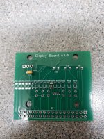
First mistake I made was the 3mm LEDs on the display board in backwards, there is not a flat on the side of a small LED. The PCB has a small dot on it for the Cathode and a square pad, the Cathode is the short leg.
Second most likely mistake is the SMD Diode on the encoder board, there is a polarity stripe on the top of the diode, not easy to see but it goes to the edge of the board, not towards the center as I did on one of the boards. You know you got it wrong when the button push of the encoder doesn't mute the preamp.
And finally be careful crimping the Insulation Display Connectors, IDC, on the ribbon cables, smaller ones are easy but I let the cable slip on a long connector as I tightened the vice. If that happens and the cable doesn't work you can lift the ears of the connector gently, pop off the top and remove the ribbon cable for another try, just don't pull straight up on the cable, kind of start at one side and roll the cable out of the cutters so it doesn't pull any of the cutters pins from the connector.
A tip for the header to Arduino Mega board connectors, put the headers into the Mega connectors, put the assembly on the underside of the lower, long, PCB and solder the pins, this keeps them lined up perfectly so you will be able to plug and unplug the Mega from the main board easily, if you need to, I haven't had to yet.
Most everything else is fairly obvious, If you have a lead forming tool then use it on the volume resistors for a good looking board, .8 width.
Happy building.
So my friend called me the other day having built a couple more units of the volume control and asking which board is Left channel and which is Right. Since this iteration has balance control it matters, and the board isn't labeled. I had to look at the schematic, and the Arduino Mega pin out, and the code to determine that the upper board is the Left channel and the lower main board is the Right channel. I have one set of boards built up and saved for code development and I had written on the top board an L for left. If I ever turn the boards I will add the labeling to the silkscreen.
@johnhenryharris have you built the volume boards with both types of resisitors? Did you hear any difference? Just curious.
I have built the volume boards with both the Vishay RN series and the commerial grade of them and I cannot hear any difference, though the difference in distortion levels has to be extremely small. The Magazine Linear Audio had an article on different resistor distortion and the Vishay RN65 were very good and is what I used in my preamp, but they are approximately $60 more for the set than the commercial grade. My Audio business friend listened to both versions and couldn't hear any difference so went with the commercial grade Vishay/Dale resistors. So, your choice, either way it will sound very good.
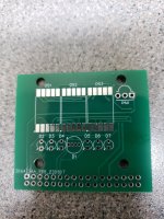
@johnhenryharris on the V3.0 Display Board, are D2, D3, D4, D5, D6 and D7 populated? They are not listed on the BOM and not quite sure what they would indicate since D1 indicates almost everything.


Well damn, don't know how I missed that one, the BOM should have six 3mm blue leds and display the balance. The D1 is an RGB LED, Blue is active, Red is Mute, Green is standby. There should have been a line like this on the BOM:
| Blue LED, display | 3.2fv 20ma | D2-D7 | C4SMK-BJF-CQ0T0352 | 941-C4SMKBJFCQ0T0352 | M | 4 | 4 | $0.18 | $0.72 |
OK, that makes sense. I'll add them to my next order. I populated the volume encoder board and about half of the display board tonight. Had to order the power supply board and input encoder board from JLCPCB, missed those the first time around. Making progress. Mouser doesn't have the 20 position cable ends. I'll search for them from somewhere else tomorrow.
Well, I have egg on my face again. The part number listed for the 20 pin IDC cable end was wrong, it was for a 24 pin. So, I have fixed the part number for the cable end and added the LED line to the BOM. There are over 3000 20 pins in stock at mouser. Here is the updated BOMs. So hard to cross check every part number in a timely manner.
Attachments
- Home
- Source & Line
- Analog Line Level
- Preamp Control - Volume, input, mute, remote