you can degenerate your higher Idss jFETs down to a more managable Id, that suits the Buffer.......................
Anyway, your #3 suggestion above seemed like the logical choice, so I found a nice closely matched pair of 8.27mA JFET's and soldered them in one channel. Sure enough, within a couple of minutes of powering it up, the heatsinks were noticeably warmer than the other channel which still had the lower Idss devices soldered in place.
Unfortunately, probably about 1/3 of my batch of 5102's measure between 4-5.9mA or over 10mA. I'm not sure what I can do with these devices that fall outside the preferred range of 6-10mA................
If you meet the 2times Vp rule then a high Idss used for the master (follower) can have a source resistor fitted say around 1r to 5r to bring the Id down to roughly similar to the Id of the 8.27mA Idss devices.
Measure the Id and Vds of the 8.27ma devices.
Find what rs is required to make the high Idss device pass the same current at the same Vds.
The disadvantage to this method is slightly lower gm of a high Idss device operated at a very low Id. As far as I know this effect is quite small and almost certainly inaudible.
Inductor Value: ~1µH-2,2µH
This is where I got the figure of 10uH from...must be an error in the assembly guide.
Attachments


10uH inductors.
Will these work instead of wrapping wire around a round object?
RLB1314-100KL Bourns | Mouser
Rated at 2.7A, .015 ohms DCR and cheap.")
Will these work instead of wrapping wire around a round object?
RLB1314-100KL Bourns | Mouser
Rated at 2.7A, .015 ohms DCR and cheap.
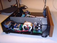
Calvin, I will try and sketch the components that my PRE is consisting of.
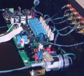
First (Image 1): the PSU - section.
230VAC mains enters the case through a SCHAFFNER-filter.
The PE-connector of the filter's output is connected to the metal bottom plate of the case (chassis PE-earth).
I have also connected the R-Core's screen wire to the chassis.
These are the only wires / signals that I have connected to the chassis!
The Schaffner-filter is followed by a DC-hum filter.
(I have already bypassed the hum-filter, but this did not change anything.)
The used R-Core provides 2 x 9VAC @ 350mA each and 2 x 18VAC @ 650mA each.
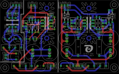
The R-Core connects to the PSU shown in image 2.
The PSU consists of 3 sections: a +5VDC / +8VDC on the left side for the passive PRE, a +5VDC for the DAC and a +/-18VDC for your buffer on the right side.
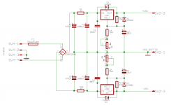
The "Buffer-PSU" is using a traditional LM3x7 ddesign (see image 3).
The 3 sections of the PSU work "independently" from one another.
The GNDs of the 3 sections are not connected to each other.
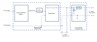
The source signals pass through a selection relay (see image 4), the LDR-attenuation and the mute relay.
The source's return-wire is not connected to GND on the passive PRE-PCB.
I have placed a 3-pole connector (Out-Left, Out-Right, Signal Return) on the output of the mute-relay.
When I run some wires from this connector to the RCA connector in the back-plane and connect an amplifier to it, everything works fine.
When I connect the output of the mute-relay to the buffer (see pink arrow on image 5), I have a persistent awful hum.
The funny thing is:
- I am able to perfectly adjust your buffer
- Looking at the buffer's output with my oscilloscope, I see very well shaped sine and square waves.
What could be the reason for this strange behaviour?
Best regards - Rudi
P.S.: The buffer-PCB is shown in post #617.
First (Image 1): the PSU - section.
230VAC mains enters the case through a SCHAFFNER-filter.
The PE-connector of the filter's output is connected to the metal bottom plate of the case (chassis PE-earth).
I have also connected the R-Core's screen wire to the chassis.
These are the only wires / signals that I have connected to the chassis!
The Schaffner-filter is followed by a DC-hum filter.
(I have already bypassed the hum-filter, but this did not change anything.)
The used R-Core provides 2 x 9VAC @ 350mA each and 2 x 18VAC @ 650mA each.
The R-Core connects to the PSU shown in image 2.
The PSU consists of 3 sections: a +5VDC / +8VDC on the left side for the passive PRE, a +5VDC for the DAC and a +/-18VDC for your buffer on the right side.
The "Buffer-PSU" is using a traditional LM3x7 ddesign (see image 3).
The 3 sections of the PSU work "independently" from one another.
The GNDs of the 3 sections are not connected to each other.
The source signals pass through a selection relay (see image 4), the LDR-attenuation and the mute relay.
The source's return-wire is not connected to GND on the passive PRE-PCB.
I have placed a 3-pole connector (Out-Left, Out-Right, Signal Return) on the output of the mute-relay.
When I run some wires from this connector to the RCA connector in the back-plane and connect an amplifier to it, everything works fine.
When I connect the output of the mute-relay to the buffer (see pink arrow on image 5), I have a persistent awful hum.
The funny thing is:
- I am able to perfectly adjust your buffer
- Looking at the buffer's output with my oscilloscope, I see very well shaped sine and square waves.
What could be the reason for this strange behaviour?
Best regards - Rudi
P.S.: The buffer-PCB is shown in post #617.
Attachments
Last edited:
Hi Rudi,
1. Did you try listening to the buffer without anything connected to its' input?
2. In your PSU, it looks like some 120uF to 470uF capacitors at its' outputs are called for. Right now the outputs have 10uF capacitors in series with 240R resistors, which isn't enough.
1. Did you try listening to the buffer without anything connected to its' input?
2. In your PSU, it looks like some 120uF to 470uF capacitors at its' outputs are called for. Right now the outputs have 10uF capacitors in series with 240R resistors, which isn't enough.
Joshua: the hum is present, even if no input (CDP, ...) is connected to the PRE (I need to verify this once more and ask my DIY-friend Hans).
I have placed 2 x 100µF capacitors on the buffer PCB near the PSU-connector (have a look at the image in post #617 please).
Best regards - Rudi
I have placed 2 x 100µF capacitors on the buffer PCB near the PSU-connector (have a look at the image in post #617 please).
Best regards - Rudi
Last edited:
As Calvin wrote in post #621, you probably have GND loop problem. Disconnected GND or wrong connected or audio GND running through power GND or......
Are all of your grounds (Dac GND, buffer GND, ....) connected together or floating?
Can you draw a schematic diagram for connections?
Are all of your grounds (Dac GND, buffer GND, ....) connected together or floating?
Can you draw a schematic diagram for connections?
@Stormsonic:
The different GNDs of DAC, PRE and Buffer PSU are not connected to one another.
AUDIO GND (Signal Return) is not connected to either DAC or PRE GND.
It connects of course on the entry to the buffer PCB with the buffer - PSU - GND (have a look at image 4).
Best regards - Rudi
P.S. Joshua: I have sent you a PM.
P.S.,
Nothing connected to the input of the buffer means also not the ground from the preamp.
If when nothing is connected to the input of the buffer there will be hum, it means that something is wrong with the buffer, or with its' PSU.
If when nothing is connected to the input of the buffer there will be no hum, it means that there is a ground loop between the preamp and the buffer.
It's part of the Thiele Network that virtually all amplifiers use to help with maintaining stability.What's the purpose of the resistor paralleled with the inductor?
However, using an inductor alone to drive a reactive load will result in ringing and that ringing frequency will depend on the L & C values.
To suppress the ringing you add resistance to damp out the resonance.
For typical speaker loads of 4ohms to 8ohms we generally use 0.5uH to 6uH with a parallel damping resistor from 1r0 to 10r0.
I think the top end values of both these two ranges are far too high for normal speakers. I suggest 0.5uH to 1uH parallel with 1r0 to 5r0 as a reasonable range for normal speakers.
- Home
- Source & Line
- Analog Line Level
- Preamp-Buffers - simple idea