Hi,
You mean the JFET-PNP CFP instead of the JFET-JFET-casode? So we could talk of a CFP²")
Hmmm, it´d certainly run the input stage at higher currents, but the JFETs at very low currents. One will have to test if that´d come with a sonic penalty or an improvement.
Will have to hack that into a sim asap
jauu
Calvin
You mean the JFET-PNP CFP instead of the JFET-JFET-casode? So we could talk of a CFP²
Hmmm, it´d certainly run the input stage at higher currents, but the JFETs at very low currents. One will have to test if that´d come with a sonic penalty or an improvement.
Will have to hack that into a sim asap
jauu
Calvin
I mean now that you slowly drifted into (SM) CFP, and it proved to be a huge benefit in the LTP, then why not continue to try it in the buffer too, it would remove the fairly lowish voltage over the buffer input Jfet. As I see it a CFP pair is a much better current source.
I changed the input in my Power-amp, with more than 20 dB improvement in distortion figures. I think that is impressive. To further improve the "constant power input", one could insert a driven(hawksford) cascode. (but that would somehow seem over the top)
I changed the input in my Power-amp, with more than 20 dB improvement in distortion figures. I think that is impressive. To further improve the "constant power input", one could insert a driven(hawksford) cascode. (but that would somehow seem over the top)
Last edited:
Hi,
it seems that further reductions in THD would be only of academical interest.
What could be interesting would be a increased overhead and of course the useage of easier to source and cheaper parts.
First sims replacing the upper JFET (4391) by a bipolar FZT751 for a hybrid-CFP instantely worked with also impressingly low THD figures. But the output ran on too much current and the current distribution between the transistors in input and output stage of the Buffer seems a bit tricky. I´m still searching for the right tuning wheels to dial in on sensible mA-values.
jauu
Calvin
Hi,
thanks for the tip MiiB. Got a set of values now so that the whole circuit runs on ~50mA idle current and the JFETs still not starving and still all SMD parts possible.
Two things improved.
THD seems even lower and still with a nice harmonic ditribution and the overhead increased considerably to ~8.5Vrms with +-15V supplies.
jauu
Calvin
ps. think I´ll also sim a fully bipolar asap
The lower distortion is not the real goal, but it reflects much more linear device combinations they simply work in a more ideal way. purer devices gives purer results. At some point in time I'll try to implement the hawksford cascode as well, then I believe we would have an ideal constant power input block. that will have the least change of working parameters with applied signal, and thus would exhibit the least amount of memory type distortion.
Hi,
just a short note.
I got the all-bipolar version running.
Even lower distortion. Figures are now perversly low
Overhead limit remains at ~8Vrms for +-15V supplies.
Compensation caps have to be moved from the output transistors to between the collectors of Master and slave and probabely need to be increased in value to keep the thing from oscillation. Of course means to bias the slaves have to be added.
More on this later.
jauu
Calvin
just a short note.
I got the all-bipolar version running.
Even lower distortion. Figures are now perversly low
Overhead limit remains at ~8Vrms for +-15V supplies.
Compensation caps have to be moved from the output transistors to between the collectors of Master and slave and probabely need to be increased in value to keep the thing from oscillation. Of course means to bias the slaves have to be added.
jauu
Calvin
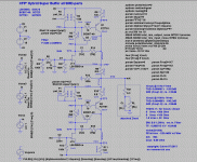
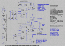
Hi,
CFP² Hybrid and CFP2 all bipolar Super Buffers SMD attached.
You could replace Cp/Rp by an RC combo of 150p/10R for the hybrid and 100p/6R8 for the bipolar version.
The bipolar version comes with the drawback of requiring bias means and due to this input coupling caps.
jauu
Calvin
CFP² Hybrid and CFP2 all bipolar Super Buffers SMD attached.
You could replace Cp/Rp by an RC combo of 150p/10R for the hybrid and 100p/6R8 for the bipolar version.
The bipolar version comes with the drawback of requiring bias means and due to this input coupling caps.
jauu
Calvin
Attachments
Last edited:
I was not really thinking the bottom current source also, but that may also be a good idea, here you have the CCS modulated, but I am not really sure weather the CCS should have have high impedance as main priority or weather the voltage modulation headroom is the highest priority. To me it would make sense to cascode the CCS and to CFP the input. a sort of cascode CFP hybrid.
Hi,
the ´mixture´ of the CFP2 for the Follower part and the cascoded JFET CFP for the modulated current source part sims still well, but not as well as the pure versions. All 3, the cascoded complementary JFET CFP as well as the Hybrid-CFP2 and the all-bipolar CFP2 sim better (20-30dB lower THD).
The mixed verion also asks for a higher number count of different parts and a different PCB layout of follower and current source subassembly.
In short, everything speaks in favour of the symmetrical versions.
And between the three, I´d omit with the all-bipolar buffer, since it requires DC-coupling caps and additional parts and effort for biasing and trimming.
jauu
Calvin
- Home
- Source & Line
- Analog Line Level
- Preamp-Buffers - simple idea