May be a too simple/stupid question...but as I am planing to build a new PP with an interstage transformer:
What are your thoughts or experiences of those which have build both concepts...
a. One driver tube: sakuma pp - Google-Suche
vs.
B. two in PP, which is quiet what you typically expect like here http://www.nutshellhifi.com/Karna.gif
?
I would expect quiet a different sound signature...but have never build a PP with just one driver tube...?
Last edited:
If you really mean Sakuma style the signature will be surely different. He was not really interested in HiFi as commonly intended but was rather looking for some very vintage sound. That's why those strange transformer's ratios etc.in his designs...
If you only mean IT as SE-to-PP drive, it might be just as good or better in theory however in practice PP-to-PP IT's nowadays can be made really transparent with outrgeously wide bandwidth and tiny distortion. Something you can't get close with SE-to-PP IT. For example a PP-to-PP IT can have much higher inductantooce and can use bifilar windings if 1+1:1+1. You can't use bifiar on SE-to-PP because there is not "enough symmetry".
Nonetheless the SE-to-PP IT can be quite good if a certain approach is used. Once the driver requirements are established you have basically two ways: 1) decide which the circuit and tubes use and get the IT abult round it, 2) get the best IT (mnimum compromise) amd design the rest around it.
Disregarding distortion, where a differential stage wins hands down, SE and PP have their distinct sets of problems.
SE is simple, but the requirement for primary DC current puts conflicting limitations on the driver tube. The lower Rp the better, but low Rp means high current through transformer's primary. This can be seen using an example of UTC HA-133, one of the best SE to PP interstage transformers. HA-133 is rated 15 K at 8 mA. For rated low frequency performance, driver's Rp should be 20-25% of transformer's primary impedance, but tubes that have Rp of 4K at 8 mA do not exist. Closest would be a tube like 26 (Rp=7.3K at 6.2 mA), but higher than optimal Rp will limit low frequency response.
The main problem of PP to PP transformers is DC current imbalance. A good PP to PP transformer cannot tolerate even a small DC current imbalance. For example, the maximum primary DC imbalance for UTC HA-107 is only 0.25 mA, which is difficult to achieve without resorting to balancing servos, which have their own set of problems. Another approach is to use driver tubes that idle at low current, for example 01A at 3 mA. The acceptable 8% imbalance can be achieved by careful matching and voltage stabilization. Unfortunately, if IT drives a PP triode stage, 01A driving capability is insufficient.
So, pick your poison.
A good PP to PP transformer cannot tolerate even a small DC current imbalance.
A good PP to PP transformer should tolerate a small DC current imbalance, as almost always there is DC current imbalance.
Proper balance of core dimension and air gapping, in order to preserve inductance and permeability as much as possible, is the most appropriate way to handle this.
The same holds for PP output transformers.
PP transformer with a gap is by definition not good - it is compromised. Gap dramatically reduces core permeability, requiring higher number of turns to compensate for lost inductance, or loss of bandwidth if one accepts decreased inductance. With high number of turns, winding capacitance and leakage inductance present much bigger problems than with low number of turns. Gain in one area (DC balance), loss in other (bandwidth and self-resonance).
Well, if I am looking at some of the tubes I have on hand to play this role of a driver Se-->PP, I believe their rp would not ne so bad to do the job actually:
- 801A: rp in reality around 3.5k measured
- 814A in triode around 1.5k
- 4p1l in triode 1.5
All of them can easily be run at 30mA or more...to have enough power to actually not compromise transient response...I guess the question indeed becomes how good can an IT be build when it handles in SE 30mA...compared to PP...
On PP and balancing...I bought about 80 4p1l and match them using utracer at the operating point I am using in the amp. So, matched them for emission, rp, mu, and mA/V. Few are left when you try to match all parameters. Even when you try your very best: Still I got at 30mA in PP differential pairwith a CCS in the cathode a current difference of 2mA between the two legs. Dont know how you would get this smaller as matching has been done already like hell...
PP transformer with a gap is by definition not good - it is compromised. Gap dramatically reduces core permeability, requiring higher number of turns to compensate for lost inductance, or loss of bandwidth if one accepts decreased inductance. With high number of turns, winding capacitance and leakage inductance present much bigger problems than with low number of turns. Gain in one area (DC balance), loss in other (bandwidth and self-resonance).
So you actually say that SE transformers can not be good because they need airgaps
 .
.Once more: it is a matter of finding the right compromise (as in all transformers).
Maybe you better stick with parafeed?
IME a Lynn Olsen style amplifier will give better specs (input phase splitter - PP interstage transformers).
A good quality SE : PP interstage transformer might sound equally good, but they are very difficult "animals" to wind.
Anyway, I am out of this discussion.
PP transformer with a gap is by definition not good - it is compromised. Gap dramatically reduces core permeability, requiring higher number of turns to compensate for lost inductance, or loss of bandwidth if one accepts decreased inductance. With high number of turns, winding capacitance and leakage inductance present much bigger problems than with low number of turns. Gain in one area (DC balance), loss in other (bandwidth and self-resonance).
A small air gap will always be present unless one uses an un-cut core. The only un-cut cores I know are only toroidals and R-type.
It doesn't create any problem as permeability is still considerably higher than typical SE.
Depending on the transformer and actual design, 2-5 mA DC bias is not a problem.
Even un-cut cores might tolerate a small amount of 1-2 mA (which is not small for a driver stage) because the H field doesn't collapse instantly....at least using good GOS and Hi-B GOS cores, IME.
SE IT's can be made of reasonably small size while having 100H and 25 mA DC operative current. And actually SE-to-SE can have much better frequency response than SE-to-PP because of the techniques that can be used for windings....
Forget vintage stuff. Modern transformers can count on much better cores, insulators and wires....
Last edited:
You might not need 30mA. So what do you want to do with such SE-to-PP driver?Well, if I am looking at some of the tubes I have on hand to play this role of a driver Se-->PP, I believe their rp would not ne so bad to do the job actually:
- 801A: rp in reality around 3.5k measured
- 814A in triode around 1.5k
- 4p1l in triode 1.5
All of them can easily be run at 30mA or more...to have enough power to actually not compromise transient response...I guess the question indeed becomes how good can an IT be build when it handles in SE 30mA...compared to PP...
On PP and balancing...I bought about 80 4p1l and match them using utracer at the operating point I am using in the amp. So, matched them for emission, rp, mu, and mA/V. Few are left when you try to match all parameters. Even when you try your very best: Still I got at 30mA in PP differential pairwith a CCS in the cathode a current difference of 2mA between the two legs. Dont know how you would get this smaller as matching has been done already like hell...
As I said earlier, you basically have two ways to do it. I think that establishing the requirements for the amp and then designing the driver stage around a transformer that has satisfactory perfomance is usually better.
I want to drive a pair of 814A, maybe alternatively 300B or EML520v2, but first of all a pair of 814A (in triode).
Last question from my side for the moment: What are your thoughts about PP:SE, for example as an OPT in a linestage ? I would guess that a normal PP-IT with a small airgap can be used as DC is really only flowing on the primary side ?
Plus a PP secondary is basically the same as a SE secondary, with the only difference that "minus" is floating/not grounded (I believe I have seen quiet a bit of schematics where people are not even use a CT being grounded, but feed just plus and minus to the following diff. pair, where the grid-to-ground resistors give both signals their potential/splitting)
Last edited:
The two can not be compared, the former is designed by an "enthuiast" without any sort of electronic training, and the latter is designed by two competent engineers. Lo-hi vs. hi-fi...a. One driver tube: sakuma pp - Google-Suche
vs.
B. two in PP, which is quiet what you typically expect like here http://www.nutshellhifi.com/Karna.gif
The 814a in triode mode might require some positive grid drive for good efficiency. SE-to-PP IT is not the best choice for this tube, IMHO. But you can try if efficiency is not your main concern....
300B might be better but still not the ideal tube. For example you could use the the Lundahl LL1692a/18mA in SE-to-PP connection but with primaries in series (so it's a modified ALT V connection). This way you will have 3.5:2+2 transformer with 95H inductance and 21 mA DC capability. I think the 801A run at 20mA anode current will be enough for swinging the required voltage for class A1 or AB1 operation.
High freuqency response should be just good enough with 20-25 KHz @-1 dB.
Even un-cut cores might tolerate a small amount of 1-2 mA (which is not small for a driver stage) because the H field doesn't collapse instantly....at least using good GOS and Hi-B GOS cores, IME.[/QUOTE]
Yes. This is why bigger transformers are better. IMO, bigger core is a better solution than gap.
Again yes. Achieving symmetry comes at the cost of higher winding capacitance, which compromises the bandwidth. SE to SE is free of symmetry problems. But symmetry is the key to true differential operation, which eliminates 2nd harmonic. So, when striving to achieve lowest distortion, the extra cost of good SE to PP transformer is entirely justified, IMO.
This is arguable. For an amateur, it doesn't matter if you pay $200 for a modern or vintage transformer. The UTC transformers I mentioned were top notch professional units used by recording studios and FM broadcast stations. I cannot forget transformers like HA-107 or HA-133 simply because modern equivalents are nonexistent. Lundahls are good, no question, but their standard transformers use grain-oriented steel cores, and units with amprphous cores (still inferior to UTC HA cores) are two times the price. Lundahl's offerings are all low impedance, so you can forget about using them with such favorite tubes as 26 or 01A. Yes, there are better cores, insulation, and wire, but somehow it did not translate into new equivalents of classical vintage transformers.
Yes. This is why bigger transformers are better. IMO, bigger core is a better solution than gap.
And actually SE-to-SE can have much better frequency response than SE-to-PP because of the techniques that can be used for windings....
Again yes. Achieving symmetry comes at the cost of higher winding capacitance, which compromises the bandwidth. SE to SE is free of symmetry problems. But symmetry is the key to true differential operation, which eliminates 2nd harmonic. So, when striving to achieve lowest distortion, the extra cost of good SE to PP transformer is entirely justified, IMO.
Forget vintage stuff. Modern transformers can count on much better cores, insulators and wires....
This is arguable. For an amateur, it doesn't matter if you pay $200 for a modern or vintage transformer. The UTC transformers I mentioned were top notch professional units used by recording studios and FM broadcast stations. I cannot forget transformers like HA-107 or HA-133 simply because modern equivalents are nonexistent. Lundahls are good, no question, but their standard transformers use grain-oriented steel cores, and units with amprphous cores (still inferior to UTC HA cores) are two times the price. Lundahl's offerings are all low impedance, so you can forget about using them with such favorite tubes as 26 or 01A. Yes, there are better cores, insulation, and wire, but somehow it did not translate into new equivalents of classical vintage transformers.
Just my $0.02: I'm at the moment thinking of PP with a SE front + IT. Of course, everything should be excelled as best as possible, but to my ear the PP amps sound noticeable "sweeter" with a SE front/driver stage.
Though, everything depends on a particular combination of sound source + speakers setup. If already having the source with balanced output I'd vote for differential front/driver + PP IT.
Though, everything depends on a particular combination of sound source + speakers setup. If already having the source with balanced output I'd vote for differential front/driver + PP IT.
SSer, you are operating on the assumption that a minimum gap core for PP is best. I will tell you that I have found that this is not a good assumption.
cheers,
Douglas
Douglas, could you please elaborate?
Just my $0.02: I'm at the moment thinking of PP with a SE front + IT. Of course, everything should be excelled as best as possible, but to my ear the PP amps sound noticeable "sweeter" with a SE front/driver stage.
Though, everything depends on a particular combination of sound source + speakers setup. If already having the source with balanced output I'd vote for differential front/driver + PP IT.
SE shines at low signal levels, where distortion is intrinsically low. Having SE front before the line level is totally justified, IMO. But as signal voltages increase, the benefits of differential topology become greater and greater.
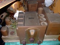
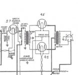
Somehow I was able to find two identical Stewart Warner R-100 radios that have 27 to IT to push-pull 45s as their audio output stage. One with all original parts still fully working after 80 years! One day I just might restore them...
Full schematic can be found on radiomuseum dot org.
Full schematic can be found on radiomuseum dot org.
Attachments
Again yes. Achieving symmetry comes at the cost of higher winding capacitance, which compromises the bandwidth. SE to SE is free of symmetry problems. But symmetry is the key to true differential operation, which eliminates 2nd harmonic. So, when striving to achieve lowest distortion, the extra cost of good SE to PP transformer is entirely justified, IMO.
Sorry you are confusing things! One can make a perfectly symmetrical SE-to-PP transformer but cannot use bifilar winding, for example, because it would not be symmetric in terms of applied DC differential.
As a consequence of this a SE-to-SE using bifilar widings can be a lot better in terms of high frequency response. Normally, for the same technique, it would be worse!
This is arguable. For an amateur, it doesn't matter if you pay $200 for a modern or vintage transformer. The UTC transformers I mentioned were top notch professional units used by recording studios and FM broadcast stations. I cannot forget transformers like HA-107 or HA-133 simply because modern equivalents are nonexistent. Lundahls are good, no question, but their standard transformers use grain-oriented steel cores, and units with amprphous cores (still inferior to UTC HA cores) are two times the price. Lundahl's offerings are all low impedance, so you can forget about using them with such favorite tubes as 26 or 01A. Yes, there are better cores, insulation, and wire, but somehow it did not translate into new equivalents of classical vintage transformers.
They were top notch in their time they are not today, sorry. And it is not just because of the core material but also insulators and wires. For sure they didn't have anything like Nomex, for example. That already makes quite a big difference. I would never spend 200$ for 50 years old (or more) transformer. That's just crazy for me.
Lundahl transformes are good value but aren't really the best transformers around. Amoprhous cores is not a good material, IMHO.
Best materials for IT transformers are those with reasonable low loss, high enough saturation (to avoid proposterous transformers) and high intial permeability. Armorphous is actually poorer than high grade GOS in terms of permeability and saturation.
Using bigger cores than needed is not good design for me because it might improve low frequency performance and copper loss but it will cause even more troubles at high frequency and the latter is a bigger issue for IT's.
- Status
- This old topic is closed. If you want to reopen this topic, contact a moderator using the "Report Post" button.
- Home
- Amplifiers
- Tubes / Valves
- PP with IT: One or two driver tubes ?