A KISS regulator here:
http://www.dissident-audio.com/AutoIndex/index.php?dir=RegulHT/&file=Regul.html
Apologies for the langage that I use, picture should be self explanatory
Yves.
http://www.dissident-audio.com/AutoIndex/index.php?dir=RegulHT/&file=Regul.html
Apologies for the langage that I use, picture should be self explanatory
Yves.
hey-Hey!!!,
Just a note, the output Z of the regulator is not so important. It should be constant, but the required screen stopper has always been *MUCH* larger( at least with TV sweeps ).
Screen voltage should probably get set for lower distortion v. maximum power. That is set to a level that drives the load line to g1=0V to the right of the knee. Taking it through the knee will raise the odd HD while allowing the valve to swing slightly more voltage.
cheers,
Douglas
Yvesm said:A KISS regulator here:
http://www.dissident-audio.com/AutoIndex/index.php?dir=RegulHT/&file=Regul.html
Apologies for the langage that I use, picture should be self explanatory
Yves.
Yves,
That is a neat one. Have you tried it with cascode MOSFET's yet? I see a benefit to its HF response, especially on the pass device.
cheers,
Douglas
Hi Douglas !
The goal was to show the "KISSEST" way to build a HV regulator, of course the door is open for improvment I could eventually add to the article with credits to the author(s).
Apart from this "diversion", adjusting independently the screen voltages in a PP (or any form of diff amp) proves to be a much more efficient way to balance both dynamic and static behaviour than just setting grid bias for DC balance cos this affects the transconductance too.
Checked that when trying to match very hi but very different Gm "video" pentode (EL802: 30000 to 45000)
F.E., plate curves superposed near perfectly with one sample at 100Vg2 and the other one at 150V.
Adjusting grid bias just "moves" the curves up and down and you can only match at one point while adjusting Vg2 make'em "streching/unstreching" like an accordion
Yves.
Not every French people love accordion !
Yvesm said:Hi Douglas !
Adjusting grid bias just "moves" the curves up and down and you can only match at one point while adjusting Vg2 make'em "streching/unstreching" like an accordion
Yves.
Not every French people love accordion !
hey-Hey!!!,
That is one of the better discriptions of the effect I've seen so far...I think I'll use it...
cheers,
Douglas
Wavebourn said:One shunt regulator with a source follower is more than enough for a highest quality amplifier, but in such case control grid bias must be regulated as well!
Indeed !
Regulate both or none, but never only one
If possible, use shunt reg for the grid bias so it can absorb unwanted grid current when overdrive occurs.
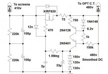
ray_moth said:This is my preferred screen stabilizer at present. What do you think?
Simplicity will do for screen regulation.
However those HV zeners with all the drift aren't for me.. Why the 75 ohm resistor ? .. You are relying on the 33uF for ripple rejection; the o/p could use a single 450V o/p cap.
My favourite would to use a 2nd mosfet and an ic to do the dirty regulation work. .
O.M.O.
richy
ray_moth said:This is my preferred screen stabilizer at present. What do you think?
I use one resistor where you use a complex CCS.
Yvesm said:I use a resistor where you use zeners !
Current being constant, voltage is constant too . . . .
See post #21 above.
Is your CCS more stable than my Zeners? Is it less temperature dependent?
Do you know why do I cover the 1'st tube circuit in my gyrator loaded amps? Shielding from electro-magnetic garbage and coupling is one reason; another reason is I am getting an infra-sound signal when I blow on MOSFETs in gyrators.
Wavebourn said:
Is your CCS more stable than my Zeners? Is it less temperature dependent?
Do you know why do I cover the 1'st tube circuit in my gyrator loaded amps? Shielding from electro-magnetic garbage and coupling is one reason; another reason is I am getting an infra-sound signal when I blow on MOSFETs in gyrators.
CCS might help isolate PS noise allowing a much simpler PS filter.
I use the same CCS + resistor arrangement for G1 fixed bias because
it's stable and adjustable. There does not seem to be much drift as
the MOSFET warms up. I think it is within 1-2% in the first second or so.
Is your MOSFET on a heatsink? Very interesting... Mine don't seem
to be that sensitive but it's something to look for. Could it be more
sensitive at higher current?
Michael
Michael Koster said:
CCS might help isolate PS noise allowing a much simpler PS filter.
I use the same CCS + resistor arrangement for G1 fixed bias because
it's stable and adjustable. There does not seem to be much drift as
the MOSFET warms up. I think it is within 1-2% in the first second or so.
Is your MOSFET on a heatsink? Very interesting... Mine don't seem
to be that sensitive but it's something to look for. Could it be more
sensitive at higher current?
It is BSP225, heatsink is a copper resistor lead soldered to it, current is 8 mA, voltage is 100V. The whole amp has 27 dB amplification, and infra sound disturbance when I blow on it is about 10 millivolts (against 100V P-P max needed swing), i.e. -66 dB approximately.
Edit: typos corrected
Wavebourn said:
Is your CCS more stable than my Zeners? Is it less temperature dependent?
Dunno !
But check GE-MOV or SIOV as hi voltage zeners ersatzs.
Smoothest knee of course and large shunt capacitance (who cares for a shunt regulator ?) but much lower temperature drift.
Knee voltage is around 1.6 to 1.8 the marked value.
Yves.
Yes, it's their primary usage !
But I've some running for many years, as long as current is limited and pwr dissipated remain low, they seem able to survive without damage.
Discovered incidently their low thermal drift characteristics when checking simple circuits to regulate vidicon's focus voltage ... long time ago !
Nothing about that in mfr specs
Yves.
Yvesm said:Yes, it's their primary usage !
But I've some running for many years, as long as current is limited and pwr dissipated remain low, they seem able to survive without damage.
Discovered incidently their low thermal drift characteristics when checking simple circuits to regulate vidicon's focus voltage ... long time ago !
Nothing about that in mfr specs
Thank you many-many times!
Screen Regulators I
Here are two designs for active screen regulators I actually used in projects. Both are variations on the usual solid state theme. This one uses a 6AQ5 (trioded) as the seies pass device, and the 6CB6 high gain, VHF pentode as the error amp. The 6CB6 works nicely here since it has a higher than usual Vhk rating.
Here are two designs for active screen regulators I actually used in projects. Both are variations on the usual solid state theme. This one uses a 6AQ5 (trioded) as the seies pass device, and the 6CB6 high gain, VHF pentode as the error amp. The 6CB6 works nicely here since it has a higher than usual Vhk rating.
Attachments
Re: Screen Regulators I
http://wavebourn.com/images/audio/HP400.pdf
Miles Prower said:Here are two designs for active screen regulators I actually used in projects. Both are variations on the usual solid state theme. This one uses a 6AQ5 (trioded) as the seies pass device, and the 6CB6 high gain, VHF pentode as the error amp. The 6CB6 works nicely here since it has a higher than usual Vhk rating.
http://wavebourn.com/images/audio/HP400.pdf
- Status
- This old topic is closed. If you want to reopen this topic, contact a moderator using the "Report Post" button.
- Home
- Amplifiers
- Tubes / Valves
- PP pentode screen supply