The left channel seems to be taking much more current. I'm not sure which is correct.
The output stage screen resistors should be mounted right on the g2 pin, so they act as screen stoppers. Not inches away on a tag strip. Generally you seem to have long wires. OK for a guitar amp with big grid stoppers, but not so good for hi-fi as it gives valves the chance to oscillate at RF.
Making the input stages mirror images of each other is a good way to increase the chance of wiring errors, and make subsequent fault-finding harder. There are good reasons why stereo loudspeakers are sometimes done as mirror images, but these reasons don't apply to circuitry.
There are lots of DC voltages missing from the circuits. On the right channel, is the lower driver cathode really at 385V?
An oscope is invaluable here. What you want to do (I hate to give an engineer advice because I'm only a ET) is disconnect any feedback and troubleshoot each side seperately starting in the middle (I forgot what they called it in the Navy), preferably on the left side. See how much hum you have on the driver tube's grid, even 10mv, go backwards until it disappears. If there is none, then move forwards until it shows up.
If you have 385 volts on the cathode of that driver, the resistor has to be open or not connected correctly. One thing that would help us, is putting all the component values on the schematic, along with all voltages of the tubes.
I do like the new component placements. Looks alot neater, and no flying connections. Grid stopper resistors and screen stopper resistors need to be directly connected to the tube sockets. You need to add grid stoppers to the KT88s control grids. Usually 1-3K, preferably carbon composition, carbon film is ok too.
Can we see the top of the chassis?
Last edited:
Update!
The 385 [V] at the cathode was because of a wiring mistake. Unfortunately, I also mixed the grids for one KT88 and now the tube is toasted, however I had a replacement from a previous amp.
I disconnected the negative feedback... And holy smoke this thing works! And it sounds good!
The voltages from the PS are a bit high but I reworked the loadlines and they are actually pretty good. All the biases are around <1[V] from each other and from each channel, however now I'm dissipating around 6[W] from the cathode of the KT88s so I ordered some 10[W] wirewound resistors. I can't listen to music for too long because the solder gets hot and that bypass resistor comes off, this should be fixed with the WW resistors...
I guess this is good news! But I'm still confused why the NFB didn't work, and why it created hum on only one side... Jones Morgan's Valve book doesn't do a very good job explaining NFB, so I guess I'll have to research that.
If anyone has any input on the NFB, I would appreciate it. Also I'll be posting a picture of the top of the chassis soon.
And again, thanks to everyone who's thrown in their 2 cents... It has been really helpful!
With the cathode resistor doing around 6 watts, the KT88s should be going close to 40 watts each. Are you in class A doing push pull? KT88s can do 45 watts, but at 40 watts they will have a shortened life. You can increase that life by going into AB1 and about 30 watts each. You can also put a small negative voltage on the grid resistors of the KT88s of about 10-15 volts to help the tubes out and the cathode resistors. Of course with self bias you'll want a push pull output transformer at about 5K to 6K primary. Fixed bias is about 4.2K primary.
Maybe you have too much feedback. Put in a test signal and get 10 volts out of the amp. Replace the feedback resistor with a 22K and see what voltage you get out. Keep replacing the resistor with lower values until you get about 5 volts out of the amp. See what it sounds like with the resistor in and out.
Maybe you have too much feedback. Put in a test signal and get 10 volts out of the amp. Replace the feedback resistor with a 22K and see what voltage you get out. Keep replacing the resistor with lower values until you get about 5 volts out of the amp. See what it sounds like with the resistor in and out.
Ok, so the amp is working without feedback and it sounds pretty good, but I was expecting it to be much better. There is one last issue that I can't figure out:
The right channel sometimes you a hear some sort of a... sputter? spitting? It happens at loud volumes but I can't find a pattern, it seems to happen with high volume and at sudden quick surges of volume within the music. It even makes the cones on the speakers "jump". What can I look for to find what might be causing this? I'm a bit dumbfounded since it doesn't happen at low volumes and I can't seem to replicate it when I want it, also I don't want to damage my speakers hehe.
Any ideas??
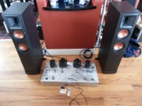
Oh! And here's a pic of the amp:
The right channel sometimes you a hear some sort of a... sputter? spitting? It happens at loud volumes but I can't find a pattern, it seems to happen with high volume and at sudden quick surges of volume within the music. It even makes the cones on the speakers "jump". What can I look for to find what might be causing this? I'm a bit dumbfounded since it doesn't happen at low volumes and I can't seem to replicate it when I want it, also I don't want to damage my speakers hehe.
Any ideas??
Oh! And here's a pic of the amp:
Attachments
Could be RF oscillation. This can be sensitive to signal levels, because to the accidental RF oscillator you may have built the audio signal is a varying bias. Add grid stoppers to the output valves.
The problems when you close the feedback loop may be loop instability. Have you done a Bode plot? Four stages plus an OPT can generate a lot of phase shift at frequency extremes.
The problems when you close the feedback loop may be loop instability. Have you done a Bode plot? Four stages plus an OPT can generate a lot of phase shift at frequency extremes.
DeathRex: I'm using JJ GZ34, and if I hook up the feedback then the left channel gets crazy loud hum (even without music) and the right channel is very quiet.
DF96: I did, the bode plot looks good up until 17 kHz, then it got kinda funky. However, I don't understand how this could be the problem since it appears to happen randomly and the left channel doesn't exhibit this problem.
DF96: I did, the bode plot looks good up until 17 kHz, then it got kinda funky. However, I don't understand how this could be the problem since it appears to happen randomly and the left channel doesn't exhibit this problem.
I haven't been able to check anything when the feedback is connected for that channel. It is so loud I have to turn it off and I don't have a resistor box handy to load the output.
Also, I'm worried something might get damaged since the only measurement I was able to make was at the grids and the voltages were huge. Something is causing that feedback to not work, this is my first time working with F.B. so I don't really know what to do. I calculated those resistor values using Morgan's book, but he didn't explain very well that math. Finally, why would one channel exhibit a problem and now the other? They are (supposed to be) identical.
And it wasn't wiring, since I completely re did it a couple weeks ago. I swapped tubes from sides and nothing.... No idea what to do here.
WITH FEEDBACK:
-Left Channel: LOUD hum/distortion. (All grid voltages are huge)
-Right Channel: Quiet music
WITHOUT FEEDBACK:
-Left Channel: Works perfectly.
-Right Channel: Works but at high volumes you get random violent sputter/distortion/spitting.
Have you checked and double-checked that the left channel has negative feedback and not positive? Try greatly increasing the value of the feedback resistor. At some point you should find that the left channel problem disappears, as you approach the 'no feedback' state. Now does the (small amount of) feedback increase or decrease gain, when compared with no feedback?
I'm not sure wiring could be the issue, I redid all my wiring already.
I guess tomorrow what I'll do is:
- Hook back the feedback and increase that resistor value.
- Put grid stoppers for the KT88s.
- Measure if the feedback is positive or negative (still not sure how to do this).
I'll report back tomorrow.
I guess tomorrow what I'll do is:
- Hook back the feedback and increase that resistor value.
- Put grid stoppers for the KT88s.
- Measure if the feedback is positive or negative (still not sure how to do this).
I'll report back tomorrow.
One of the problems with debugging your own circuit/build is that any misconceptions you have can propagate. Checking a mistake against your own misunderstanding when the misunderstanding is the cause of the mistake can lead to the situation where you are sure everything is right, yet it still doesn't work: clear evidence that something is not right.
I have told you how to check whether the feedback is positive or negative. Reduce the feedback, then see if it raises or lowers gain. The normal amount of feedback will either greatly reduce gain (if the loop is stable), or cause oscillation. If the loop is unstable then both positive and negative feedback will cause oscillation, but at different frequencies.
I have told you how to check whether the feedback is positive or negative. Reduce the feedback, then see if it raises or lowers gain. The normal amount of feedback will either greatly reduce gain (if the loop is stable), or cause oscillation. If the loop is unstable then both positive and negative feedback will cause oscillation, but at different frequencies.
- Status
- This old topic is closed. If you want to reopen this topic, contact a moderator using the "Report Post" button.
- Home
- Amplifiers
- Tubes / Valves
- PP KT88, Need help!