Hint: what is the formula for working out the output V in terms of input V and feedback V?
The effect of feedback is to reduce the open loop gain. The less feedback the less the open loop gain will be reduced. Under what special case do the feedback resistors set the closed loop gain exactly?
The effect of feedback is to reduce the open loop gain. The less feedback the less the open loop gain will be reduced. Under what special case do the feedback resistors set the closed loop gain exactly?
PMA said:But closed loop gain can never be greater than that estimated by feedback resistors. If yes, then I have to give back my university diploma.
You don't need to give back your university diploma...you are right!
But maybe a new theory is coming around the corner...
mandat said:I think that input JFETs shoul have ID about 50 mA for driving output MOSFETs effectively. Does exist such a JFET on the market?
As the output Mosfets in this circuit have voltage gain they don't need to much voltage swing in his gate...so they are more easy to drive , than the usual source folower...
Have you ever wished you hadn't said anything at all? The new theory is that I cannot do simple algebra. You guys are right. I have no explanation for the unexpected measurements.But maybe a new theory is coming around the corner...
Sorry for any frustration my diversion may have caused!
(PMA - how to I get one of those diploma things?)
argo said:Maybe the Nobel Prize should go to this guy here:
http://www.ne.jp/asahi/evo/amp/J200K1529/report.htm
Translation (Babelfish) of the Japanese text for that circuit:
This is the circuit which first is tried in taking of experiment. As for the first level in the complimentary differential circuit, as for the output step it made the complimentary push pull circuit of source ground operation, it made minimum 2 stage constitution as a power amplifier. The idling electric current of 2SJ200/2SK1529 is adjusted 0.5A with the variable resistor 100 Ohm. As for installed capacity by 8 Ohm loads approximately 50W, as for output resistance 0.8 Ohm about, it is the simple circuit by 8 Ohm loads, but even this way it becomes sufficient utility. If as for open loop gain of this amplifier in order the extent whose load impedance is low to decrease, being inversely proportional to load impedance, output resistance increases and output resistance 0.8 is Ohm by 8 Ohm loads, when by 4 Ohm loads as for output resistance 1.6 Ohm, becomes conversely by 16 Ohm loads as for output resistance 0.4 the extent damping whose load impedance is high in the condition which is called Ohm good, load impedance becomes low, becomes suddenly damping bad. As for MOS-FET of the output step because degree of curve of VGS-ID characteristic curve is large in the part whose drain electric current is little, idling electric current with 0.1A generates the big third distortion factor. MOS-FET being there is no necessity, does, drive electric current with the voltage input element, but when frequency becomes high, because electric current is consumed in the charging and of Ciss, electric current amplitude of the first level differential amplifier becomes large and the third distortion factor increases. In addition, because with 2SJ200 and 2SK1529 Ciss is different, the extent push pull balance whose frequency is high deteriorating, the secondary distortion factor increases.
No mentioning of supernatural closed loop gain, only that the output impedance is inversely proportional to the load impedance, resulting in bad loudspeaker damping for low impedance speakers.
Steven
Steven said:
Translation (Babelfish) of the Japanese text for that circuit:
This is the circuit .....
No mentioning of supernatural closed loop gain, only that the output impedance is inversely proportional to the load impedance, resulting in bad loudspeaker damping for low impedance speakers.
Steven
Exactly. Anyhow without trying to prove anything, this is what my trusty simulator comes up with:
Attachments
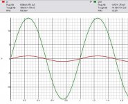
The simulator results is in line with post #17 circuit where feedback resistors gives a gain of abut 20 (corrected schematics as compared ot original circuit in earlier post) but since the open loop gain is relatively low then the real close loop gain is about 14 something.
Ouf, I can keep my diploma!
Fab
Ouf, I can keep my diploma!
Fab
Quote: "but even this way it becomes sufficient utility". This is the line that made want to build this amp. I didn't have the monolithic jfets, so I just used what I had. Glad to see it brought about some discussion. I also remeber taking a reading from the output of one of the Diff. pairs and that they did have gain. The voltage was somewhere around 4 Vpp ( again using a 3.27 Vpp input sine wave. However I don't remember if this was with the complete circuit or without the output transistors. I guess I'm not that comcerned with what the formula for the gain is, I know how I can adjust it to get the desired output. I love the Japanese schematics that are out there and its even more fun to try and read the sites using translation.
Anyway, all bickering about the formula for gain aside, where would some ppl go with this amp as far as modifications. I am curious, tho I will probably complete another channel and finish this one at some point.")
-D
P.S. With the input fets that I used and the 10K feedback resistor makes the amp clip completely.
Anyway, all bickering about the formula for gain aside, where would some ppl go with this amp as far as modifications. I am curious, tho I will probably complete another channel and finish this one at some point.
-D
P.S. With the input fets that I used and the 10K feedback resistor makes the amp clip completely.
Tube_Dude said:
You don't need to give back your university diploma...you are right!
But maybe a new theory is coming around the corner...
I'm still with Jorge here.
Standard feedback equations...
Av = Ao / ( 1+AoB). Av = closed loop gain, Ao = openloop gain, B = feedback factor
say Ao = 10, B = .2
Av = 3.33
Say Ao = 100, B = .2
Av = 4.76...
Clearly, with a fixed B, as Ao increases, Av increases. What is the limit? 1/B or in this case, 5....
traderbam said:Hint: what is the formula for working out the output V in terms of input V and feedback V?
Lets try following traderbam's suggestion:
Vout = Aol(Vin - Vfb).
Lets suppose we take the given numbers, Acl = 10, Vin = 3, Vout = 30 (well, aproximately what was given). Lets solve for Vfb.
30 / Aol = Vin - Vfb.
=> -Vfb = 30/Aol -3
=> Vfb = 3 - 30/Aol.
Since we know that the amplifier is noninverting, Vfb MUST be greater than 0 (ie, inphase with the input signal). We also know that Aol is not a negative number.
3 - 30/Aol > 0.
=> 30/Aol < 3.
=> 30 < 3*Aol.
=> 10 < Aol.
put this together with above...
0 < Vfb < 3
Since Vfb = B * Vout,
B = Vfb / Vout.
0 < B < .1
Wait a minute... With the given schematic, B = .2. It is mathematically not possible for a B of .2 to obtain the results given...
traderbam, please tell us what we're missing that is gonna make us eat our words.
--
Danny
fab said:The simulator results is in line with post #17 circuit where feedback resistors gives a gain of abut 20 (corrected schematics as compared ot original circuit in earlier post) but since the open loop gain is relatively low then the real close loop gain is about 14 something.
Ouf, I can keep my diploma!
Fab
Right. The sim plot posted is with 10k/510R feedback resistors. I am writing from another computer and I don’t have the sim file with me now but the gain of Dozuki's schematic with 2.2k/510R feedback resistors was close to 3 according to simulator, if I remember correctly (I used 2sj162 /2sk1058 for outputs though).
I want to try these amp!
HI
I want to try the (Nobel Price )amplifier at the 17th post .
After my knowledge these is a Class A/B amplifier .
Did anybody already built it ? There is nothing about the power supply! I have two toroid each 25-0-25V 250VA ,i think two of that will be enough .
My question how I set up the QC? If I wish to have 100mA or more ?
I have some of those Thoshiba power mosfets so I want to use them .
Thanks for any information
Regards
Hello,
Why not try the F5 instead, from Nelson Pass? Close but even more simple and with the famous so called "current feedback". You can't go wrong with this one, a lot of positive comments and a detailed article. Also very close from a Plantefeve amp (Zenotron). Just google it.
Why not try the F5 instead, from Nelson Pass? Close but even more simple and with the famous so called "current feedback". You can't go wrong with this one, a lot of positive comments and a detailed article. Also very close from a Plantefeve amp (Zenotron). Just google it.
i ll give it a try
i like it too i actually thing that somebody should creat some permened thread called " simple amplifiers " or why not "cheap amplifiers " .... not that i want to take away any honour from pass labs ....but just to have something else
i will construct to listen ...and also i dlike to bring this thread back to life and listen from others that constructed
by the way ..... so much posting about the gain of the amp ..... the simulators ...and so on ... and nobody speaks about how the amp actually sounds ....if it sounds nice it can have as much gain as it likes people !!!!!
Now though there is already no stock,
#29 type (D output) AMP KIT below
http://www2.ocn.ne.jp/~san-ei/mos50kbkit.htm
SA-50KB
http://www2.ocn.ne.jp/~san-ei/newMOSkit.htm
SA-MOS
It's caled one of "KUBOTA SIKI (TYPE) MOS-FET" amp in (only) Japan ...
and the shop is now closed..
REGARD
#29 type (D output) AMP KIT below
http://www2.ocn.ne.jp/~san-ei/mos50kbkit.htm
SA-50KB
http://www2.ocn.ne.jp/~san-ei/newMOSkit.htm
SA-MOS
It's caled one of "KUBOTA SIKI (TYPE) MOS-FET" amp in (only) Japan ...
and the shop is now closed..
REGARD
- Status
- This old topic is closed. If you want to reopen this topic, contact a moderator using the "Report Post" button.
- Home
- Amplifiers
- Solid State
- PP All FET Amp