Pin 16 is missing but it's probably OK. Pin 1 of the 494 is shutting down the 494. Both ICs seem to be operating normally now.
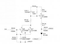
None of the schematic diagrams that I have that use similar circuits show anything other than the 293 (via 2 diodes) and a 4.7k ohm resistor connected to pin 1. Is the 4.7k resistor in the circuit and within tolerance?
None of the schematic diagrams that I have that use similar circuits show anything other than the 293 (via 2 diodes) and a 4.7k ohm resistor connected to pin 1. Is the 4.7k resistor in the circuit and within tolerance?
The 4.7 k Resistors is within tolerance ..
The output filter inductors have 2.12 volts on them im assuming this is whats making it protect..
I will check the diagrams..
Any ideas on what i should check to see if thats the cause of the 2.12 volts on the inductors?
The First diagram is the same as the one in this amp
The output filter inductors have 2.12 volts on them im assuming this is whats making it protect..
I will check the diagrams..
Any ideas on what i should check to see if thats the cause of the 2.12 volts on the inductors?
The First diagram is the same as the one in this amp
Last edited:
Is there possibly a solder bridge between the driver board pads? With no driver board, the outputs are typically held off and there is no DC.
If there are no solder bridges, you'll have to check all of the various components in the area of the outputs to see if you can find any that are leaky.
If there are no solder bridges, you'll have to check all of the various components in the area of the outputs to see if you can find any that are leaky.
- Status
- This old topic is closed. If you want to reopen this topic, contact a moderator using the "Report Post" button.
- Home
- General Interest
- Car Audio
- Powerbass XTA500D