"Normal", for classic "full wave rectifier" tube amp PSU is center tapped, which needs just 1 high voltage insulated 5V rectifier filament winding.
Now when you want to make a full wave bridge or other combinations, the sauce gets real thick, meaning multiple well insulated filament windings or in this case, separate transformers.
Quickly it becomes unefficient/antieconomic.
Now when you want to make a full wave bridge or other combinations, the sauce gets real thick, meaning multiple well insulated filament windings or in this case, separate transformers.
Quickly it becomes unefficient/antieconomic.
it is 350-0-350.
What if it is 0-350 + 0-350 ?
That means both secondaries are not connected, absolutely no continuity between them.
Is that so?
it is 350-0-350.
What if it is 0-350 + 0-350 ?
If they are 0-350 + 0-350 you can wire then in series without having the problem of DC current in the secondary
TRY THIS
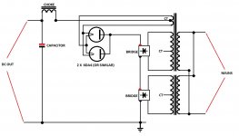
Hi....please see below circuit that I have drawn...this will work and solve your problem I have used it a number of times...hope it helps !
Hi....please see below circuit that I have drawn...this will work and solve your problem I have used it a number of times...hope it helps !
I have two identical toroid power transformers, 120V primary and 350V-0-350V secondary.
Can I wire the secondary of each transformer together in series to get 700V-0-700V ?
If I can, what should I be aware of ?
The voltage will be rectified with 2 damper diodes and the CT will be grounded.
Is there a better way to wire this up ?
Attachments
I have two identical toroid power transformers, 120V primary and 350V-0-350V secondary.
Can I wire the secondary of each transformer together in series to get 700V-0-700V ?
If I can, what should I be aware of ?
The voltage will be rectified with 2 damper diodes and the CT will be grounded.
Is there a better way to wire this up ?
yes...
a 350V-0-350V traffo is also a 0-700 traffo if you tape up the 0 lead...
so two of those makes a 700-0-700 volt traffo.....
to get the phasing of he secondary right, go ahead and connect the secondaries as 700-0-700 temporarily...
parallel connect the two primaries...
inject about 6 volts ac into the primaries...
measure the secondaries and verify that the voltages add up...
if you measure about 36 volts on each 0 to 700 volt leads but measured 0 volts on each 700 volt leads, then you got your phasing wrong....
just reverse one side of the 0-700 secondary and check again,
this time it should be ok.
- Status
- This old topic is closed. If you want to reopen this topic, contact a moderator using the "Report Post" button.