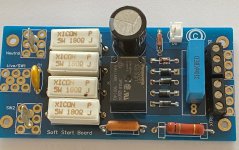
For a Dynaco ST35 would it make sense to employ the soft start board or would a CL-80 / CL-90 thermistor provide most of the benefit? TIA.
it can't harm....but for me, why bother?
Hello, I finished building my softstart and it's functioning as expected except for one annoying problem. When the switch is open, there is an audible hum coming from the board. Something weird between live/sw1 and sw2 connections. Even when I just connect neutral and live to the board it does the same thing. I am not sure where the hum/buzzing sound is coming from. If I connect live directly to the sw2 contact it turns on and the board passes the voltage and is dead silent.
Hello, I finished building my softstart and it's functioning as expected except for one annoying problem. When the switch is open, there is an audible hum coming from the board. Something weird between live/sw1 and sw2 connections. Even when I just connect neutral and live to the board it does the same thing. I am not sure where the hum/buzzing sound is coming from. If I connect live directly to the sw2 contact it turns on and the board passes the voltage and is dead silent.
Check the LED. I had this happen last night when I was fooling around connecting my oscope to various points around there and heard that just before I somehow exceeded the voltage on the LED and burned it out. Does the LED glow very bright or just a little or flicker?
I created a project page on Mouser to help people be able to do quick ordering based on the v3 BOM. https://www.mouser.com/ProjectManager/ProjectDetail.aspx?AccessID=51c6e9fdc0
HELP: 180R / 5W getting toasty
Hi guys,
Need some advice here.
I’m using a softstart board (v3) to power up an F5 amp (PSU: 400VA Toroidal transformer / 240V mains).
Even though the softstart board seems to be working well – the LED lights up and the F5 gets powered up, the R3-R6 (180R / 5W) are getting hot, so hot that even solder starts to melt.
I’ve made two changes to the original softstart BOM:
Relay: Panasonic JS1-24V-FT instead of Omron G5LA-14-CF-DC24, and
C2: 0.33uF / 275V instead of 1uF / 275V.
Any idea what’s causing the R3-R6 to get so hot?
Shall I increase the resistors’ wattage to 10W or even more?
Thanks.
Attachments
If the resistors stay hot, that would indicate that the relay is not shorting them out.
If the solder starts to melt, that's not 'seem to be working well'.
You made C2 only 1/3rd of design value. That significantly lowers the supply for the relay coil. That may be the reason it doesn't switch.
Jan
If the solder starts to melt, that's not 'seem to be working well'.
You made C2 only 1/3rd of design value. That significantly lowers the supply for the relay coil. That may be the reason it doesn't switch.
Jan
Last edited:
I reckon the 'seem to be working well' was not the best way to put itIf the solder starts to melt, that's not 'seem to be working well'.
I've changed the value based on another post that with the default value (1uF) and on 240V mains the relay would never turn on.You made C2 only 1/3rd of design value. That significantly lowers the supply for the relay coil. That may be the reason it doesn't switch.
Voltage is 13V and (unsurprisingly) no click given it’s a 24V relay.
In the meantime I’ve realized the LED is drawing too much power; by removing the LED the voltage across the relay coil jumps to 23V.
So to fix the problem I’ll choose a LED with a lower current draw and increase the value of C2 to be on the safe side.
Thanks for the help.
In the meantime I’ve realized the LED is drawing too much power; by removing the LED the voltage across the relay coil jumps to 23V.
So to fix the problem I’ll choose a LED with a lower current draw and increase the value of C2 to be on the safe side.
Thanks for the help.
Check the LED. I had this happen last night when I was fooling around connecting my oscope to various points around there and heard that just before I somehow exceeded the voltage on the LED and burned it out. Does the LED glow very bright or just a little or flicker?
The LED is ok, everything else seems ok too. I just hooked a switch directly inline and don't use the sw/1 live pad, and everything is ok that way.
1/2 second is about right. It's enough to keep the inrush current limited when the filter capacitors are empty and appear a dead short. Just a bit of charge makes the inrush quite a lot less.
The other neat trick you can do on this board is run the LED really bright - or better yet, use a higher current LED - as the location of the LED drains the capacitor during it's charge period, the brighter the LED (because brightness is controlled by current) the more delay you can add.
Hi 6L6, have you tried this...I am having slight challenge due to lot of electrical disruption at my place...summers in India means frequent power outages and distortion in supply due to power backup generators kicking in. I am more impacted due to fluctuations that is killing my fuses. The SoftStart with its stock BOM offers enough startup delay for my 45-0-45V 600VA @ 230V teddy, however it has a much longer cutoff delay on the relay once power fails (~2 sec). If power resumes almost instantly then this circuit does not really help and the fuse busts (almost as if I switch on-off-on instantaneously). I assume if we implement a brighter LED workaround will help charge C2 bit slower and increase the startup delay, would it also help in discharging the cap faster for the relay to disengage faster?? that way circuit gets ready to fireup again and manage fluctuations.
For the brightness part, we could also use a couple of LED's in parallel rather than running a single one brighter.
The v2 build guide over at Power Supply Soft Start Board (V2) might offer some tips. There's some info in there about capacitor and resistor selection and timing.
The v2 build guide over at Power Supply Soft Start Board (V2) might offer some tips. There's some info in there about capacitor and resistor selection and timing.
Thanks, gone through them, but all of them speak about startup delay, however I am looking for shortening the powerdown lag
Thanks, gone through them, but all of them speak about startup delay, however I am looking for shortening the powerdown lag
in this case, lowering the main filter dc cap to a value just enough to energize the relay will help you..
e.i. say you use 1000ufd/50v for C3, using 100ufd will discharge more quickly...but see if at that value the relay functioned...
Last edited:
kpsthakur: this may give you some guidance. You may to find a circuit with some sort of timing circuit built into it instead of this build you’re working with now.
https://www.ti.com/lit/an/slyt669/slyt669.pdf?ts=1591879454457&ref_url=https://www.google.com/
https://www.ti.com/lit/an/slyt669/slyt669.pdf?ts=1591879454457&ref_url=https://www.google.com/
Here's another PCB with free Gerbers, that implements soft start. A few details:
PCB: low voltage On-Off switch drives AC mains relay \ includes soft start .. H9KPXG
If the bypass relay contacts fail and become permanent open circuit, the ICL device is in series with the mains at all times. It is rated to withstand 7 amperes continuously; but if your Class-A power amp draws more than (7 x 115) = 805 continuous watts from the AC mains, the ICL will burn out. Then you have to replace the failed relay AND the failed ICL.
If the bypass relay contacts fail and become permanent short circuit, the AC mains will never turn off and hopefully the human user will notice! Turning the front panel switch Off, has no effect.
- Relay contacts = 16 amperes
- Inrush Current Limiter device = 22 mm, 125 Joules, 7 amps max continuous current
- Triac on/off switch rating = 16 amperes (RMS) continuous
- Delay before turn on (initiation of soft start) = 25 milliseconds
- Duration of soft start (before bypass) = jumper selection, 0.5 or 1.0 or 2.0 seconds
PCB: low voltage On-Off switch drives AC mains relay \ includes soft start .. H9KPXG
If the bypass relay contacts fail and become permanent open circuit, the ICL device is in series with the mains at all times. It is rated to withstand 7 amperes continuously; but if your Class-A power amp draws more than (7 x 115) = 805 continuous watts from the AC mains, the ICL will burn out. Then you have to replace the failed relay AND the failed ICL.
If the bypass relay contacts fail and become permanent short circuit, the AC mains will never turn off and hopefully the human user will notice! Turning the front panel switch Off, has no effect.
Hello everybody,
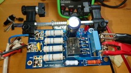
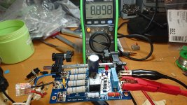
I have built the Soft Start Board for 230V.
Tested with 25V light bulb, did not light up.
C2 0.330µF
C3 1500 µF
R3-6 36 ohm for 200VA transformer
Relay does not pick up, LED does not light up.
Issue 8.89V Ac.
Relay coil 5V av 0V dc
Led 0V dc
Hallo zusammen,
ich habe das Soft Start Board für 230V aufgebaut.
Getestet mit 25V Glühbirne, hat nicht geleuchtet.
C2 0,330µF
C3 1500 µF
R3-6 36 Ohm für 200VA Trafo
Relais zieht nicht an, LED leuchtet nicht.
Ausgabe 8,89V Ac.
Relaisspule 5V av 0V dc
Led 0V dc
Attachments
Last edited:
- Home
- The diyAudio Store
- Power Supply Soft Start Board (V3)


