Thanks to Jojo to come up with this excellent softstart circuit. I have been using softstart for a long time, but the circuit I have been using is powered by a transformer. Jojo's version is powered by the mains and this not only reduces costs but also saves space. While I am rebuilding my amplifiers I think I will use Jojo's circuit.
The Build Guide suggests using 180R for R15-R18 but does not provide the formula for calculating the optimal value for the paralleled resistors. I think this resistor value can be customised to specific applications.
Here is my 2 cent contribution - Let me share with you the way I calculate the resistor value. If you find it wrong, please correct it.
It is rather simple. We only need 3 input parameters to determine the value : (1) I_limit - The desired inrush current limit; (2) Vp - The Primary voltage; and (3) Vs - The secondary voltage.
The paralleled resistors value should be: R = Vp ^ 2 / I_limit / Vs
For an example, if the primary voltage is 240VAC, the secondary voltage (before rectification) is 2 x 45VAC for two secondary windings (45-0-45, or 90VAC), and we want to limit the inrush current to 10A, then R = 240 x 240 / 10 / 90 = 64. Since we use 4 resistors in parallel, Each resistor R = 64 x 4 = 256R, and we can find the nearest value in E24 of 240R.
Note that the R has nothing to do with the size of your reservoir capacitors. The size of your reservoir capacitors does not determine the R value, rather, it determines how long it takes for the relay to click in.
The formula is based on the equation of turns ratio Vs / Vp = Ns / Np = Ip / Is. The primary current is derived from the desired current on the secondary transformed by the turns ratio then ohms law R = V / I. This assumes that the transformer is 100% efficient. In real life, the loss is very small and can be ignored.
Next, what value would I choose for C9? Actually, I would prefer to have the circuit to allow fixing C9 and replacing R13 with a trimpot for the initial setting. This would be far more convenient. Once a value of resistor is found, replace the trimpot with a resistor.
I understand that everyone recommends a couple of seconds or so before the relay clicks in. I personally don't mind a much longer time, say, 5 - 10 seconds. The reason is that, if the capacitors are not charged up yet, you want the current limit to stay on for protection. If the capacitors are already charged up, the current demand becomes so small it is completely harmless for the current to pass the resistors (unless you are already playing music at maximum volumes beyond clipping level). If not sure, model it with PSU2.
I hope this helps. I have not read through the thread. So if my information is redundant please excuse me.
Regards,
Bill
The S.S. Soft Start, as in Smooth Sailing
Populating the board was a piece of cake. Hooked it up and it worked perfect the first time out. You guys make this neophyte feel like a pro. I especially like the fact that it it hooks directly to the mains without having to buy another small transformer.
It is joined with my first ever amplifier project, Rod Elliott's famous P101. As soon as I receive my aluminum back and front plates I'll provide the official "coming out" pics. Meantime, my eyes are closed and my body is swaying to a wonderful sound!
THANX!!!
An externally hosted image should be here but it was not working when we last tested it.
An externally hosted image should be here but it was not working when we last tested it.
The S.S. Soft Start, as in Smooth Sailing folo up
BTW...I wanted to be able to have full fiddling flexibility (and especially since I'm a newbie) so I didn't want to solder the connections, fearing it would be hard to undo any goofs. So...I got 2-position Euroblocks, snapped them together, and soldered the assembly to the board. The spacing and fit are perfect, using every other terminal to connect my wires.
BTW...I wanted to be able to have full fiddling flexibility (and especially since I'm a newbie) so I didn't want to solder the connections, fearing it would be hard to undo any goofs. So...I got 2-position Euroblocks, snapped them together, and soldered the assembly to the board. The spacing and fit are perfect, using every other terminal to connect my wires.
Is the cathode of the led placed nearest to the relay ?
Thank you.
Yea my board does not have the position indicated, only two semi circles, so I was just going off the schematic.
Thank you !
Hello,
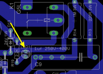
Do you see that notch in the outline of the LED? (Yellow arrow pointing on it on the attached pic.) That indicates the side for the Cathode or the shorter pin.
Try to inspect your LEDs, most 3mm and 5mm round LEDs have those notches too to indicate the Cathode.
Cheers
Attachments
and two 12V relays will operate from the same 24V circuit supplied by DIYaudio
Tony sees my posts as unhelpful.Why?
because each transformer sees it's own current limiter. and each is unaffected by what the other transformer is doing/loaded.
I am just reading this thread and sorry to go back to old posts but there is some unsafe mains advice being offered that worries me.
All (reputable) transformer manufacturers that I know specify primary side fusing requirements based on allowable temperature rise. The recommended fuse is usually a slow blow rated at 150% of the VA rating of the transformer.
All the national wiring rules that I am aware of require that each mains connected transformer has its own over-current protection to mitigate fire risks, for most of us that means a fuse. In the worst case scenario you may find your insurance company voids your cover if they investigate your claim and find non-compliance.
Therefore, and to reinforce Andrew's recommendation, mains connected transformer primaries cannot be paralleled legally or with reasonable safety.
And this of course leads to the need for 2 soft start circuits wired after the fuses.
If like me you choose to use a small transformer for the control circuitry there will be a third mains fuse.
I have seen a lot of Japanese amplifiers (circa 80"s) that had two big traffos, only one fuse, a single switch and no soft start circuit at all....
soft start circuit is indicated where there is a possibility that your power switch can get welded during turn-on.....where no such possibility exist, then there is no need for it at all...
soft start circuit is indicated where there is a possibility that your power switch can get welded during turn-on.....where no such possibility exist, then there is no need for it at all...
Folks:
If the soft start board is ever updated, would it be possible to add the capability to supply the power needed to drive the speaker protection board?
Regards,
Scott
Good point!
It's very nice that one doesn't need an extra secondary (or even extra transformer) for the softstart - but what is it good for if you still need one for the dc protection ?
Honestly I'd even prefer some small block-transformer as seen on the Vellemann K4700 directly on the dc-protection PCB.
It is not forbidden to talk about what kind of system directly connected to the mains on the forum?You can use one soft start circuit that has two outputs (from the one set on relay contacts)
BUT !!!!!!
each output needs a fuse for the transformer that output is feeding. i.e. fuse each transformer separately. This is very important !!!!!
Yet this is the same schematic as on this thread!
http://www.diyaudio.com/forums/power-supplies/235438-softstart-delay.html
It is not forbidden to talk about what kind of system directly connected to the mains on the forum?
Yet this is the same schematic as on this thread!
http://www.diyaudio.com/forums/power-supplies/235438-softstart-delay.html
Quod licet iovi non licet bovi!
Jason explains why this is the way it is, i.e. liability/insurance reasons.
For us non-US citizens this might seem strange though - but then we don't have the same laws!
Just coming to the thread
Hi,
I'm just about to start a serious F5T v.2 project.
I will use a dual mono setup: 2 x 800VA (24V) transformer feeding ~350kuF.
Actually I planned to use a CL30 in the mains as inrush limiter (like Nelson has recommended it in his F5T article). Now I'm a little uncertain if I should better use a soft start module...
And, I'm sorry for that, can someone please explain what the cap (C9?) in parralel to the mains is supposed for?
Thanks and Regards,
Kai
- Status
- This old topic is closed. If you want to reopen this topic, contact a moderator using the "Report Post" button.
- Home
- The diyAudio Store
- Power Supply Soft Start Board (V2)